


Quick Research
Generate reliable direction feasibility study reports for your R&D in just a few steps.

Technical Q&A
Discover and master advanced knowledge NOW. Basics, ideas, possibilities, all at once.

Find Solutions
As an expert in R&D theories, this can generate solutions to your technical problems instantly.

Evaluate Feasibility
Analyze your overall solution with one click, know your potential R&D risks in advance.

Monitor Landscape
Get weekly tech updates, stay abreast of the latest tech innovations and key insights.
Circuit diagram drawing board
A drawing and circuit technology, applied in the field of teaching experiment tools, can solve the problem of inconvenient understanding of circuit diagrams, and achieve the effect of convenient and flexible connection and completely consistent lines.
- Summary
- Abstract
- Description
- Claims
- Application Information
AI Technical Summary
Problems solved by technology
Method used
Image


Examples
specific Embodiment 1
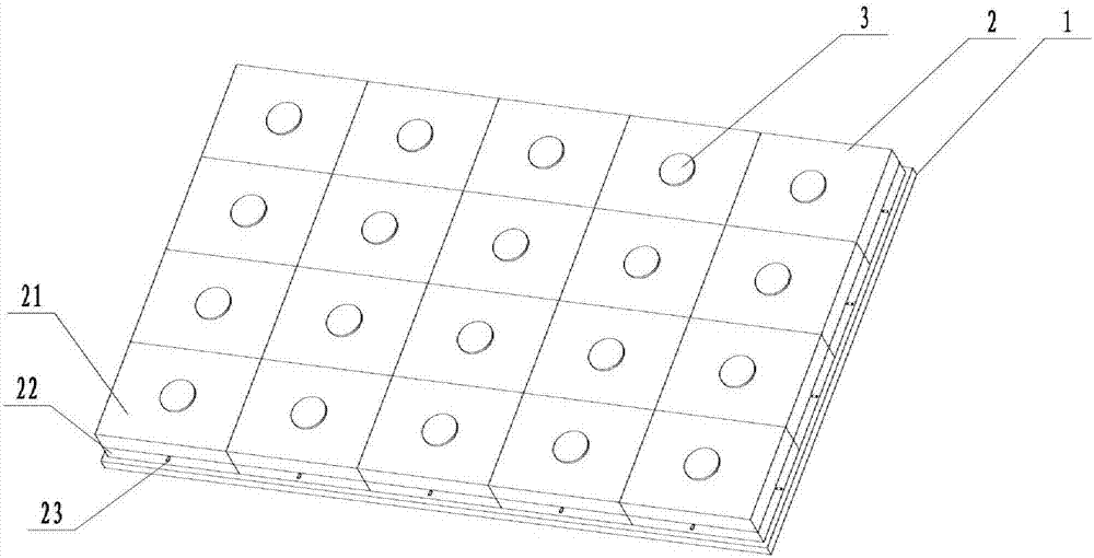
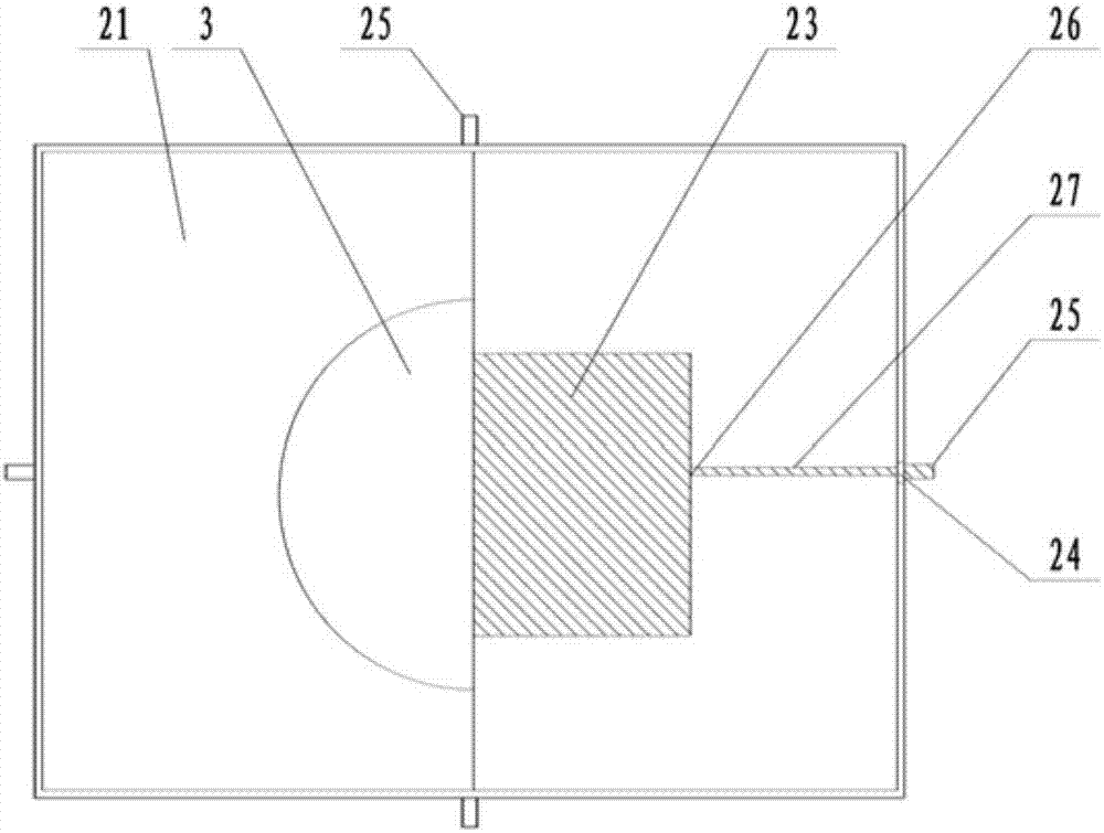
[0030] according to figure 1 ‐ image 3 As shown, a circuit drawing board includes a drawing board frame 1, a circuit module 2 and a display device 3. The drawing board frame 1 is a rectangular frame with grooves 11 arrayed in the middle, and the grooves 11 are used to define the circuit module 2 , The circuit modules 2 are in a square shape, and are uniformly distributed in the grooves 11 of the drawing board frame 1. The circuit modules 2 are restricted in the grooves 11 to prevent unnecessary wear caused by the shaking of the circuit modules 2. Closely fit, the circuit module 2 is equipped with electronic devices 23, which are fixed in the circuit module 2. The electronic devices 23 can be resistors, diodes, capacitors, switches, batteries, light bulbs, speakers, etc., or even Leads, the front and rear pins of each electronic device 23 are provided with electrical contacts 26, and the upper part of each circuit module 23 is provided with a display device 3 for displaying info...
specific Embodiment 2
[0033] according to Figure 4 ‐ Figure 7 In the circuit drawing board, the circuit module 2 further includes a control device 4, the control device 4 is erected in the middle of the housing, and the control device includes a rotary switch 41 and a guide 42. The rotary switch 41 is a cylinder. The middle of the lower housing 22 is provided with a rotating shaft 43 for rotating the rotary switch 41. The bottom of the rotary switch 41 is provided with a rotating hole 44 that matches the rotating shaft 43. The bottom of the rotary switch 41 is connected with a wire, The rotary switch 41 is a conductive body. The middle of the rotary switch is provided with an insulating layer 45 to make the upper and lower ends of the rotary switch 41 disconnected. The upper and lower ends of the rotary switch 41 are respectively provided with electrical contacts corresponding to the electrical contacts 26 on the electronic device. At point 46, there are four electronic devices 23. The electronic d...
PUM
 Abstract
Description
Claims
Application Information
 - R&D Engineer
- R&D Manager
- IP Professional
- Industry Leading Data Capabilities
- Powerful AI technology
- Patent DNA Extraction
Browse by: Latest US Patents, China's latest patents, Technical Efficacy Thesaurus, Application Domain, Technology Topic, Popular Technical Reports.
© 2024 PatSnap. All rights reserved.Legal|Privacy policy|Modern Slavery Act Transparency Statement|Sitemap|About US| Contact US: help@patsnap.com