a circuit drawing board

A picture and circuit technology, applied in the field of teaching experiment tools, can solve the problem of inconvenient understanding of circuit diagrams, and achieve the effect of convenient and flexible connection and completely consistent lines.

Inactive Publication Date: 2019-08-09
苏赫
View PDF6 Cites 0 Cited by
  • Summary
  • Abstract
  • Description
  • Claims
  • Application Information

AI Technical Summary

Problems solved by technology

[0004] In order to solve the above-mentioned problem that the existing circuit diagrams are inconvenient to understand, the present invention provides a circuit drawing board capable of performing physical connection while connecting the circuit diagrams.

Method used


Image

  • a circuit drawing board
  • a circuit drawing board
  • a circuit drawing board

Examples


specific Embodiment 1

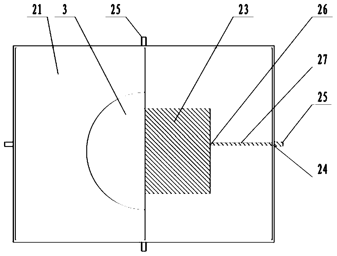
[0030] according to Figure 1-Figure 3 As shown, a circuit drawing board includes a drawing board frame 1, a circuit module 2 and a display device 3. The drawing board frame 1 is a rectangular frame with grooves 11 arrayed in the middle, and the grooves 11 are used to define the circuit module 2. , the circuit modules 2 are block-shaped, uniformly distributed in the grooves 11 of the drawing board frame 1, the circuit modules 2 are limited in the grooves 11, preventing unnecessary wear and tear of the circuit modules 2 from shaking, each circuit module 2 Closely fit, the circuit module 2 is provided with an electronic device 23, and the electronic device 23 is fixed in the circuit module 2. The electronic device 23 can be a resistor, a diode, or a capacitor, a switch, a battery, a light bulb, a speaker, etc., or even a Wires, the front and rear pins of each electronic device 23 are provided with electrical contacts 26, and the upper part of each circuit module 2 is provided wi...

specific Embodiment 2

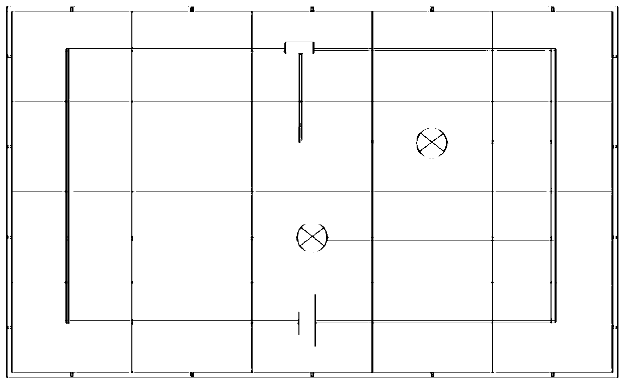
[0034] according to Figure 4-Figure 7 The circuit drawing board, the circuit module 2 also includes a control device 4, the control device 4 is erected in the middle of the housing, the control device includes a rotary switch 41 and a guide 42, the rotary switch 41 is a cylinder, and the middle part of the lower housing 22 is provided with a rotating shaft 43 for rotating the rotary switch 41. The bottom of the rotary switch 41 is provided with a rotating hole 44 that matches the rotating shaft 43. The bottom of the rotary switch 41 is connected to a wire. The rotary switch 41 is a conductor, and the middle part of the rotary switch is provided with an insulating layer 45, so that the upper and lower ends of the rotary switch 41 are not communicated, and the upper and lower ends of the rotary switch 41 are respectively provided with electrical contacts corresponding to the electrical contacts 26 on the electronic device Point 46, there are four electronic devices 23, and the ...


PUM


Abstract

The invention discloses a circuit diagram drawing board, which comprises a drawing board framework, circuit modules and display devices. The drawing board framework is a rectangular frame having grooves arrayed therein. The grooves are used for limiting the circuit modules; the circuit modules are square in shape, and are uniformly distributed into the grooves of rectangular frame in an array manner; each circuit module is internally provided with a circuit device; the circuit modules are connected in sequence; and the upper surface of each circuit module is provided with a display device for displaying information of the corresponding circuit device. By making each circuit label in a circuit diagram to be substantiated through the corresponding circuit module, virtual objects are changed into visible ones, and through modularization of each circuit device, messy shapes and different functions of carriers are limited to one circuit module, so that the circuit diagram can be connected more conveniently and orderly, connection of entities is realized while finishing connection of the circuit diagram, and it is easier to understand circuit trend in the circuit diagram and measure data of each circuit device.

Description

technical field [0001] The invention belongs to the technical field of teaching and experimental equipment, and in particular relates to a circuit drawing board. Background technique [0002] In the prior art, combined circuit modules with various electronic components as units can be combined into required circuits through mutual electrical connections, thus providing great convenience for electrical experiments and electrical teaching, so they are popular welcome. This kind of circuit module basically continues the idea of ​​printed circuit, and the electrical connection between various electrical devices often needs to be realized with the help of external wires such as circuit boards, thus restricting the flexibility of circuit changes in actual combination. [0003] In the learning process of high school electricity, students will always encounter various circuit diagrams, but except in the initial stage of understanding circuit diagrams, students can connect the basic...

Claims


Application Information

Patent Timeline
Patent Type & Authority Patents(China)
IPC IPC(8): G09B23/18
CPCG09B23/183
Inventor 苏赫
Owner 苏赫
Why Eureka
Try Eureka