
Multi-phase voltage control oscillator

A voltage-controlled oscillation and multi-phase technology, applied to power oscillators, electrical components, etc., can solve problems such as uniformity influence and difficulty

Active Publication Date: 2006-05-17
REALTEK SEMICON CORP
View PDF0 Cites 2 Cited by
  • Summary
  • Abstract
  • Description
  • Claims
  • Application Information

AI Technical Summary

Problems solved by technology

[0006] However, the uniformity of the phase difference generated by this method is easily affected by conditions such as manufacturing process or temperature, so it is not easy to achieve a uniform phase difference at high and low frequencies

Method used


Image

  • Multi-phase voltage control oscillator
  • Multi-phase voltage control oscillator
  • Multi-phase voltage control oscillator

Examples


Embodiment Construction

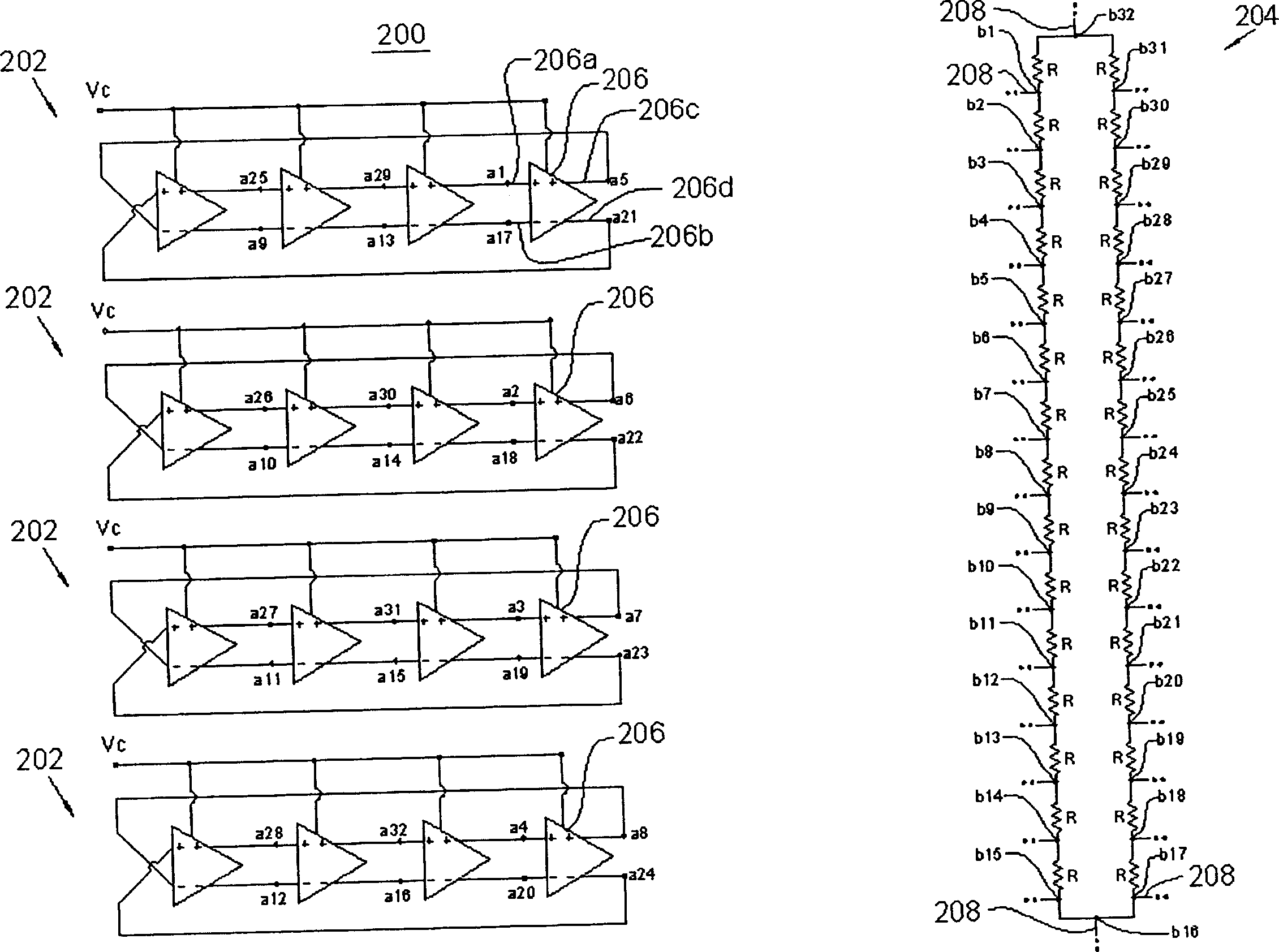
[0027] Please refer now figure 2 , which is a schematic circuit diagram of a multi-phase voltage controlled oscillator 200 according to an embodiment of the present invention. In this embodiment, the multi-phase VCO 200 can provide 32 oscillation signals with the same oscillation frequency but different phases, and the oscillation frequency of each oscillation signal can be changed by adjusting a control voltage Vc.

[0028] In this embodiment, the multi-phase VCO 200 includes four ring oscillator units 202 and a phase clamping unit 204 . Each ring oscillator unit 202 also has four differential delay elements 206, and each differential delay element 206 has two input ends 206a, 206b and two output ends 206c, 206d, wherein each differential delay element 206 has a The signal delay time is such that there is a delay between the signal on each input port 206a, 206b and the signal on each output port 206c, 206d. In addition, the signal phase difference between the input termina...


PUM


Abstract

A oscillator of multiphase voltage control consists of a ring oscillation unit formed by series- connecting a numbers of phase delay components and a resistance ring formed by series ¿C connecting a numbers of resistance components. Its features that series ¿C connected node in each ring oscillation unit is electric ¿C connected to series ¿C connected node in resistance ring to let ring oscillation unit generate a numbers of oscillating signals with uniform phase difference.

Description

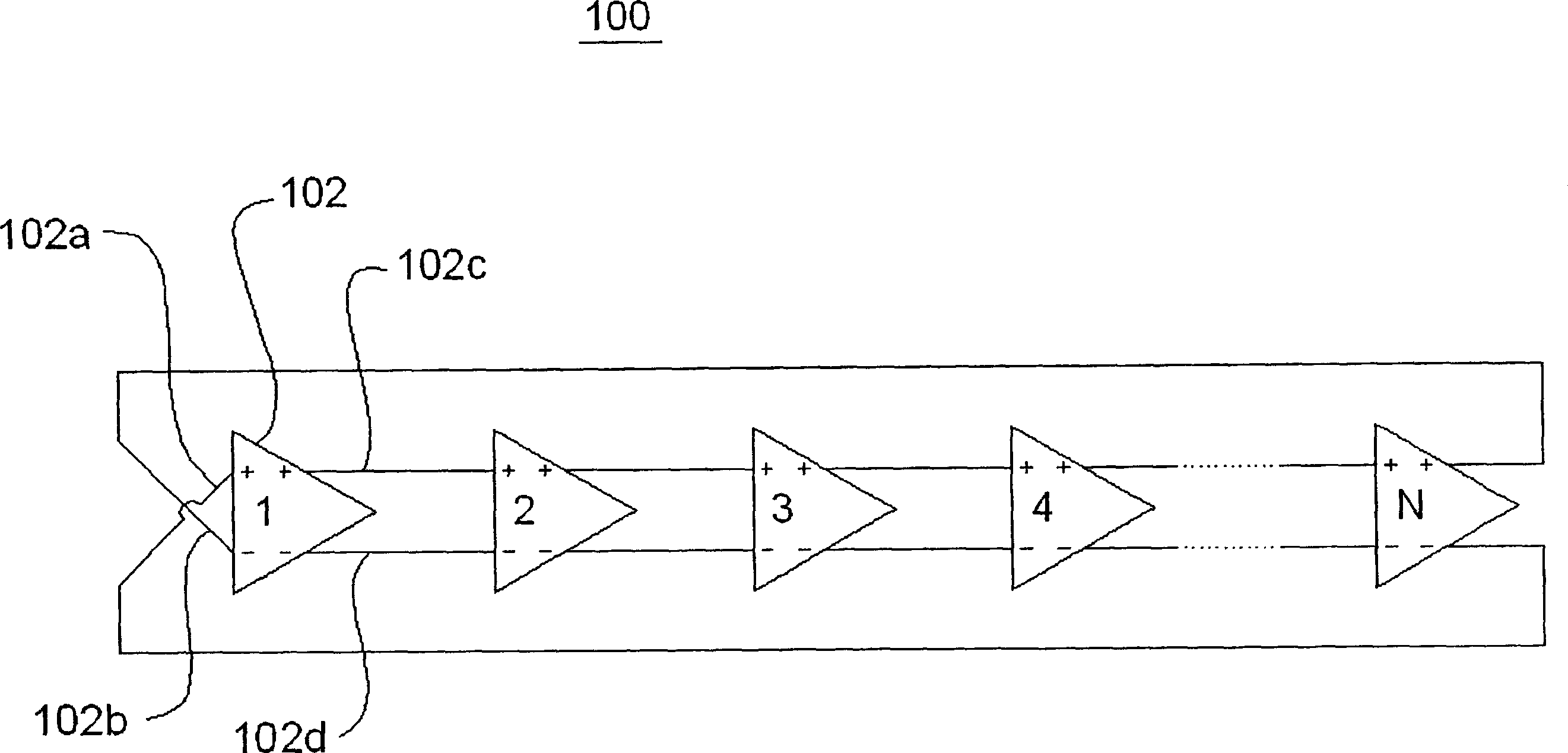
technical field [0001] The invention relates to a voltage-controlled oscillator, in particular to a multi-phase voltage-controlled oscillator. Background technique [0002] At present, multiphase voltage-controlled oscillators (VCOs) have been widely used in data-recovery systems and phase-locked loops (PLLs) circuits, which can control the magnitude of an applied voltage to output multiple Oscillating signals of different frequencies but different phases, where the frequency of each oscillating signal is proportional to the magnitude of the applied voltage. Ideally, the phases of the signals output by the multi-phase voltage controlled oscillator are evenly distributed in the phase angle range of 360 degrees, so as to achieve the best control in its application. [0003] A typical multiphase voltage controlled oscillator is formed by N delay elements, such as figure 1 shown. The multiphase VCO 100 includes N differential delay elements 102 connected in series. Each diff...

Claims


Application Information

Patent Timeline
Patent Type & Authority Applications(China)
IPC IPC(8): H03B5/20H03B5/04
Inventor 江明澄
Owner REALTEK SEMICON CORP
Learn More