Optical disk device
An optical disc device, optical disc technology, applied in optical recording head, head configuration/installation, recording/reproducing by optical method, etc., can solve the problems of deviation, tracking disturbance, tracking error signal disturbance, etc.
- Summary
- Abstract
- Description
- Claims
- Application Information
AI Technical Summary
Problems solved by technology
Method used
Image
Examples
no. 1 Embodiment approach
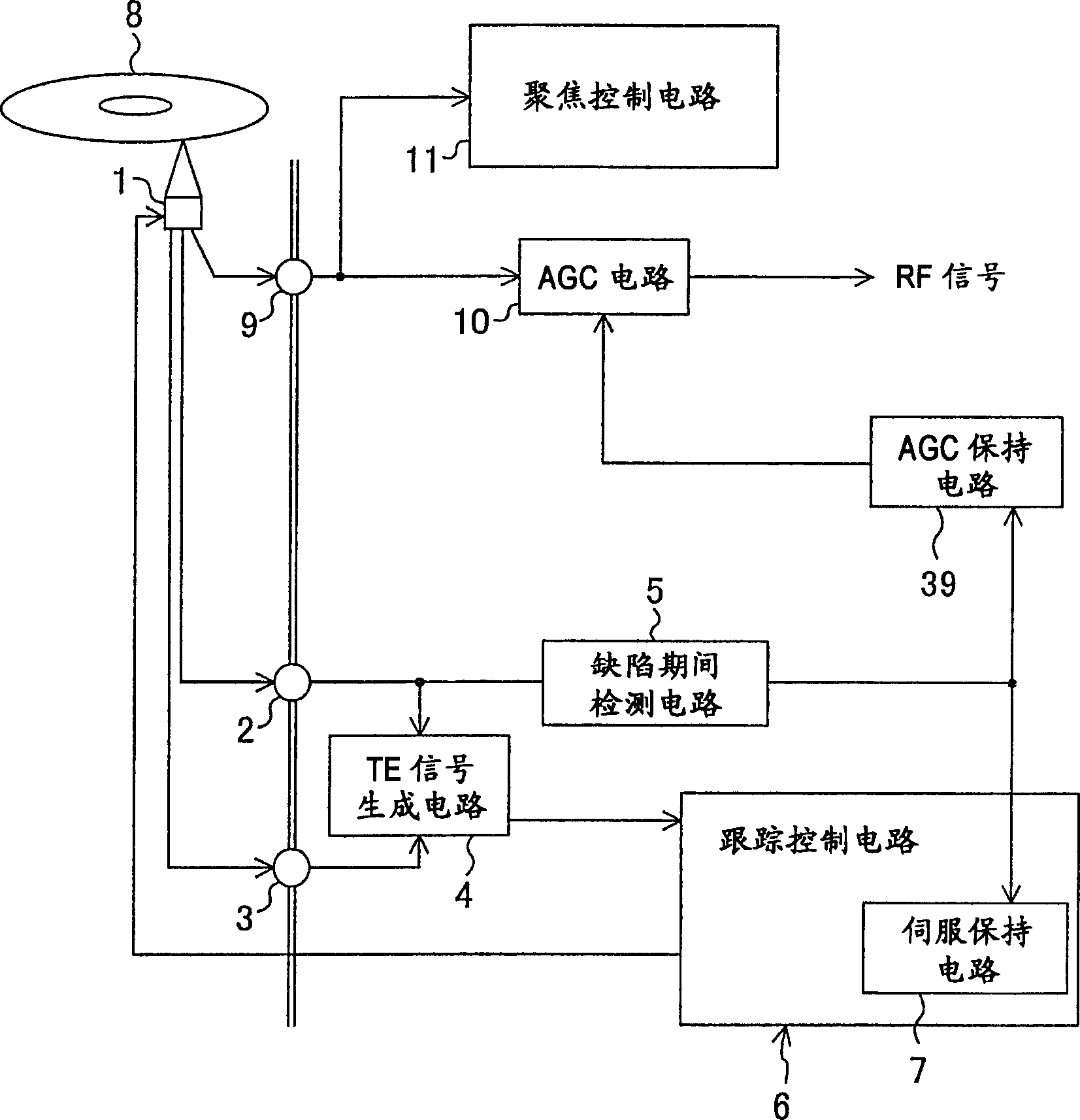
[0062] figure 1 An optical disc device according to the first embodiment of the present invention is shown.
[0063] exist figure 1 In the optical disc device shown, 1 is an optical pickup, 8 is an optical disc, 2 is a first output terminal for obtaining the return light of the preceding sub-beam, 3 is a second output terminal for obtaining the return light of the subsequent sub-beam, and 9 is for obtaining the return light of the main beam The 3rd output terminal, 4 is TE signal generating circuit (tracking error signal generating device), 6 is tracking control circuit (tracking control device), 7 is servo holding circuit (holding device), 10 is AGC circuit (AGC device), 11 is a focus control circuit (focus control means), and 39 is an AGC hold circuit (AGC hold means). The above structure, and the already described Figure 14 The optical disc device is the same, so its detailed description is omitted.
[0064] As shown in the first technical solution, the present invent...
no. 2 Embodiment approach
[0077] Figure 4 An optical disc device in the second embodiment of the present invention is shown. right with figure 1 The same symbols are attached to the same parts, and the description thereof will be omitted.
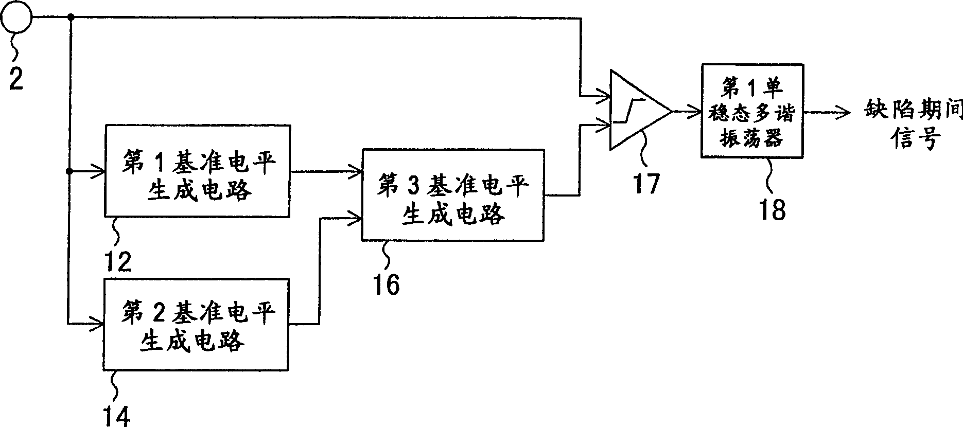
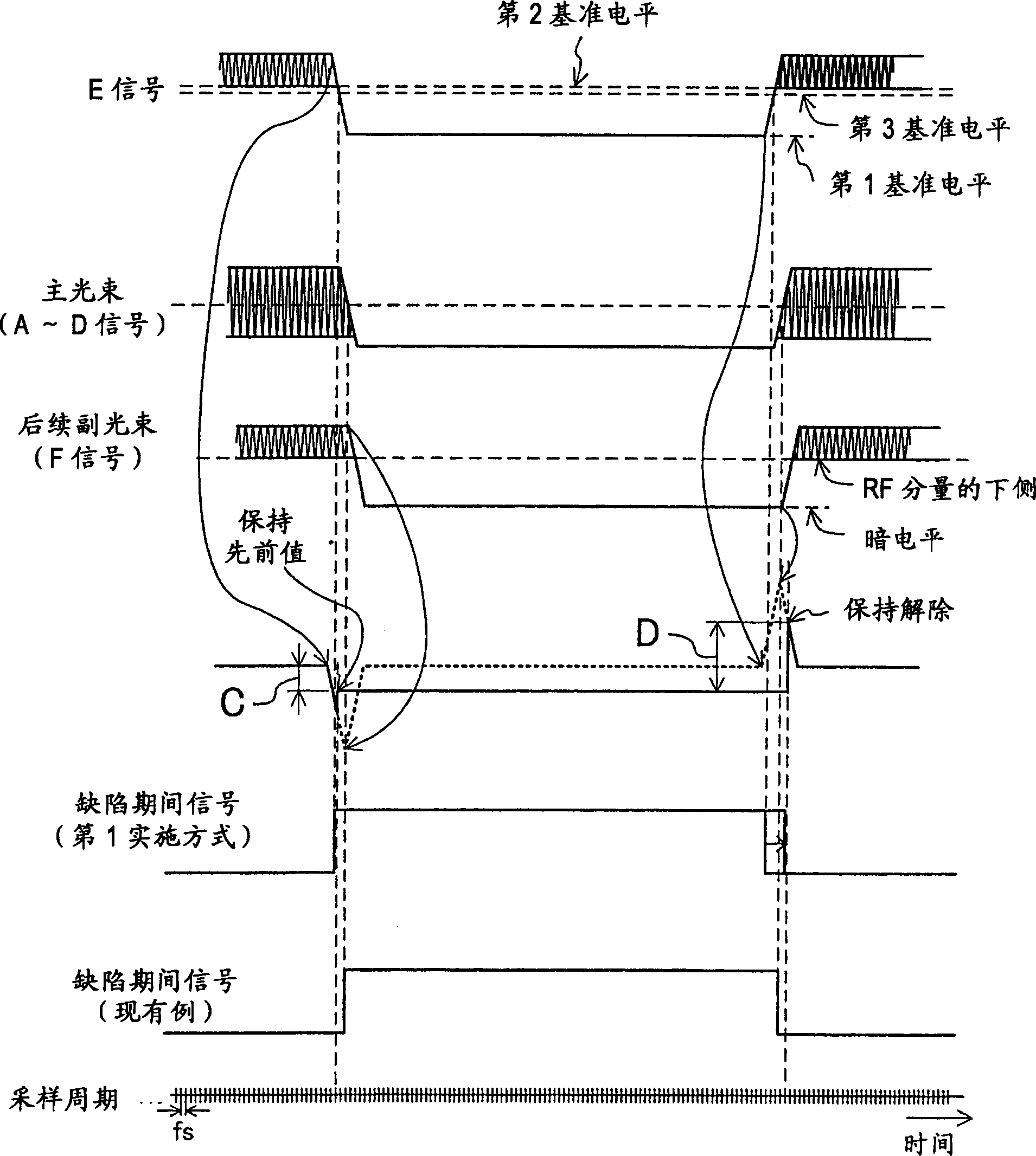
[0078] The optical disc device of this embodiment and figure 1 The difference of the first embodiment shown in the above is that the defect period detection circuit 5 is connected not only to the first output terminal 2 that outputs the E signal but also to the second output terminal 3 that outputs the F signal. Thus, the defect period can be detected by using the E signal that enters the defect period earlier than the main beam and the F signal that exits the defect period later than the main beam, thereby suppressing the amplitude of the tracking error signal when the tracking servo is maintained. It is possible to accurately detect the drop-out from the defect period, so it is possible to provide an optical disc device with little disturbance to the trackin...
no. 3 Embodiment approach
[0094] Hereinafter, an optical disc device according to a third embodiment will be described. This embodiment shows a further embodiment of the defect period detection circuit.
[0095] Figure 7 The structure of the defect period detection circuit of this embodiment is shown (sixth claim). right with Figure 5 The same symbols are attached to the same parts, and the description thereof will be omitted. and Figure 5 The difference is that a peak hold circuit and a valley hold circuit are connected between the E signal and F signal and the binarization circuit (pulse generation circuit), and a peak hold circuit and the output of the binarization circuit are connected between the above peak hold circuit and the output of the binarization circuit. Variable descent rate circuit.
[0096] Hereinafter, a detailed structure will be described. However, the structure related to the generation of the 3rd and 6th reference levels is related to the Figure 5 exactly the same and o...
PUM
 Abstract
Description
Claims
Application Information
 - R&D
- Intellectual Property
- Life Sciences
- Materials
- Tech Scout
- Unparalleled Data Quality
- Higher Quality Content
- 60% Fewer Hallucinations
Browse by: Latest US Patents, China's latest patents, Technical Efficacy Thesaurus, Application Domain, Technology Topic, Popular Technical Reports.
© 2025 PatSnap. All rights reserved.Legal|Privacy policy|Modern Slavery Act Transparency Statement|Sitemap|About US| Contact US: help@patsnap.com


