Electromagnetic interference eliminator for power system automation apparatus

A technology of automation equipment and electromagnetic interference, which is applied to electrical components, impedance networks, and AC networks to reduce harmonics/ripples, etc., to achieve good suppression effects, improve electromagnetic compatibility, and improve power quality.

Inactive Publication Date: 2006-04-26
SOUTHEAST UNIV +1
View PDF0 Cites 7 Cited by
  • Summary
  • Abstract
  • Description
  • Claims
  • Application Information

AI Technical Summary

Problems solved by technology

When the load impedance is less than 50Ω, it is suitable for low load impedance filter circuit...

Method used


Image

  • Electromagnetic interference eliminator for power system automation apparatus
  • Electromagnetic interference eliminator for power system automation apparatus
  • Electromagnetic interference eliminator for power system automation apparatus

Examples


Embodiment Construction

[0034] 1) Determination of capacitance parameters

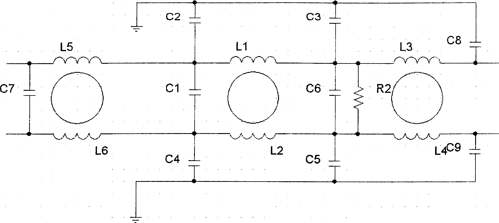
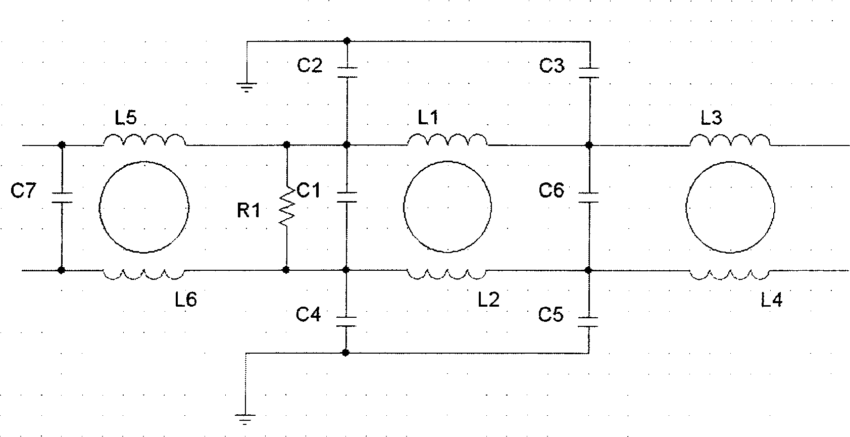
[0035] The various components in the electromagnetic interference filter such as figure 1 , figure 2 shown.

[0036] ① Determination of common mode capacitor parameters:

[0037] Select monolithic ceramic capacitors and feedthrough capacitors with good high-frequency performance as common-mode capacitors. If allowed, the larger the capacity requirement, the better, but if it is too large, the leakage current will be large. Considering the limitation of the leakage current in the design, the capacitance values ​​of capacitors C2, C3, C4, and C5 are all 2200pF, and the withstand voltage is AC 2000V; The value is 1000pF, and the withstand voltage is DC 2000V, which is suitable for high frequency.

[0038] ② Determination of differential mode capacitance parameters:

[0039] Where possible, the larger the capacity requirement, the better. In general, the required value is between 1-5uf (for each capacitor). Since the freq...


PUM


Abstract

The EMI suppressor as a power system automation device comprises a capacitor and an electric induction coil. Wherein, giving full consideration on load impedance characteristic when designing filter structure; based on testing impedance characteristic of norm port (power, PT, and CT ports), designing two norm circuits: the low load impedance filter circuit fit to condition that load impedance less than 50ª©; or else, selecting the high load circuit. This invention has strong inhibition function to ports with different impedance and fast and damped oscillation wave.

Description

Technical field: [0001] The invention relates to a device for suppressing electromagnetic interference in a power system and ensuring normal operation of power system automation equipment, which belongs to the technical field of power equipment. Background technique [0002] With the development of electric power, the problem of electromagnetic compatibility of power system is becoming more and more prominent, especially the problem of electromagnetic compatibility of automation equipment in power system is particularly important. On the one hand, the equipment itself will generate all kinds of electromagnetic interference no matter in normal working state or in abnormal working state. On the other hand, such as: high-voltage switch operation, short-circuit fault and other transient processes; high-voltage, high-current wires or electric fields and magnetic fields near equipment; radio frequency electromagnetic field radiation; lightning strikes; electrostatic discharge; vol...

Claims


Application Information

Patent Timeline
IPC IPC(8): H03H7/01H02J3/01
CPCY02E40/40
Inventor 郑建勇梁志成傅静波秦申蓓张先飞张梅陈飞
Owner SOUTHEAST UNIV
Why Eureka
Try Eureka