


Quick Research
Generate reliable direction feasibility study reports for your R&D in just a few steps.

Technical Q&A
Discover and master advanced knowledge NOW. Basics, ideas, possibilities, all at once.

Find Solutions
As an expert in R&D theories, this can generate solutions to your technical problems instantly.

Evaluate Feasibility
Analyze your overall solution with one click, know your potential R&D risks in advance.

Monitor Landscape
Get weekly tech updates, stay abreast of the latest tech innovations and key insights.
Plasma display and manufacturing method
A technology of a plasma display and a manufacturing method, which are applied in the directions of alternating current plasma display panels, cold cathode manufacturing, electrode system manufacturing, etc., can solve problems such as the collapse of partition walls, and achieve the effects of expanding discharge space, improving discharge efficiency, and improving luminous efficiency.
- Summary
- Abstract
- Description
- Claims
- Application Information
AI Technical Summary
Problems solved by technology
Method used
Image

Examples
Embodiment Construction
[0066] Below, will refer to Figure 4 Turning to FIG. 8 , an embodiment of the plasma display and its manufacturing method of the present invention will be described in detail.
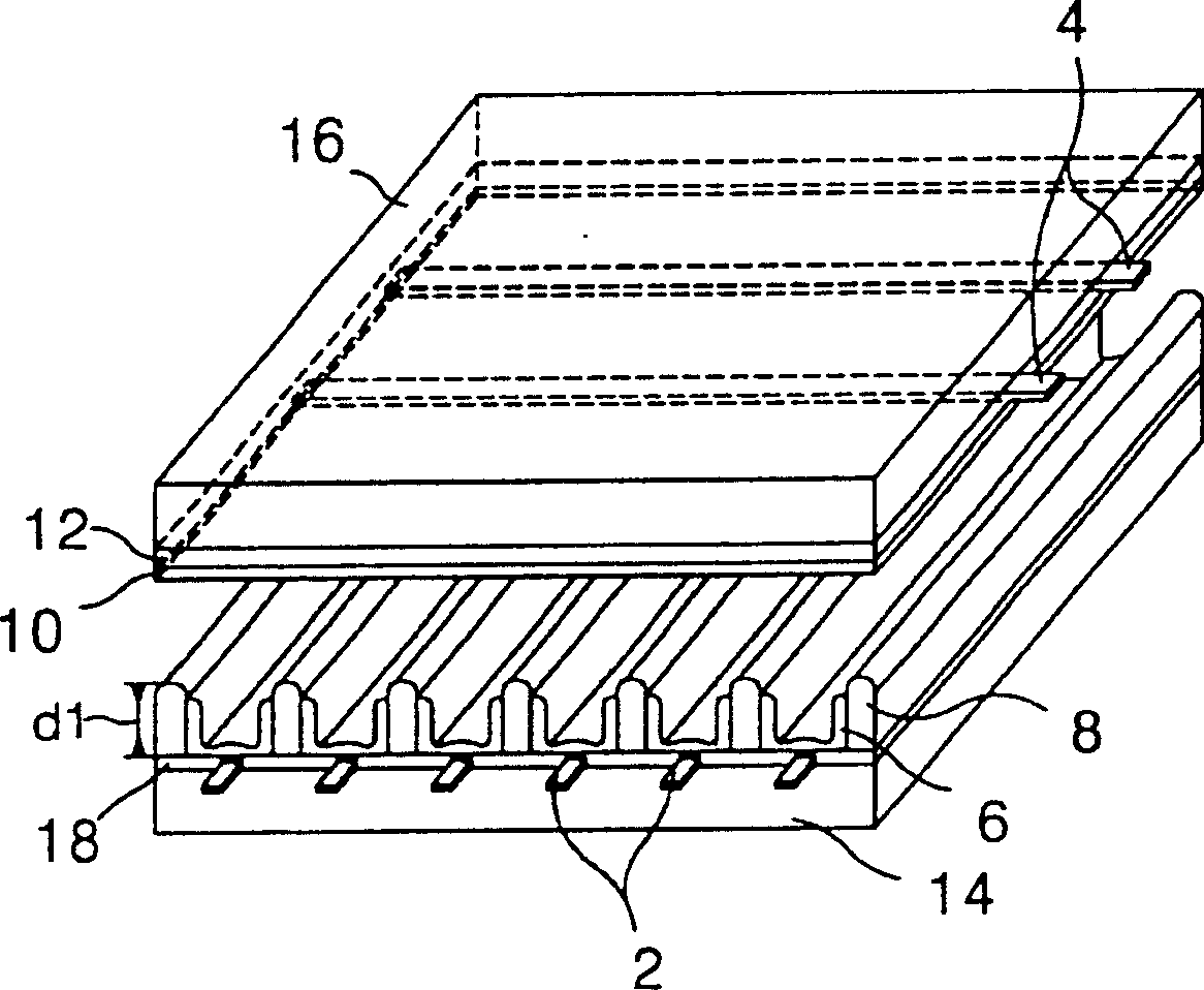
[0067] Figure 4 is a perspective view showing the plasma display according to the first embodiment of the present invention.
[0068] according to Figure 4 , represents an AC-driven plasma display having a lower substrate 114 with built-in address electrodes 102 and an upper glass substrate 116 with built-in double support electrodes 104 .
[0069] On the lower substrate 114 in which the address electrodes 102 are embedded, the partition walls 108 for dividing the lower dielectric 118 and the discharge cells are formed. The surfaces of the lower dielectric 118 and the partition wall 108 are coated with the phosphor 106 . Phosphor 106 emits light from ultraviolet rays generated during plasma discharge to generate visible light.
[0070] On the upper substrate 116 containing the dual supporting e...
PUM
| Property | Measurement | Unit |
|---|---|---|
| Depth | aaaaa | aaaaa |
Abstract
Description
Claims
Application Information
 - R&D Engineer
- R&D Manager
- IP Professional
- Industry Leading Data Capabilities
- Powerful AI technology
- Patent DNA Extraction
Browse by: Latest US Patents, China's latest patents, Technical Efficacy Thesaurus, Application Domain, Technology Topic, Popular Technical Reports.
© 2024 PatSnap. All rights reserved.Legal|Privacy policy|Modern Slavery Act Transparency Statement|Sitemap|About US| Contact US: help@patsnap.com