
Dynamic magnetic synchronous surface motor

A moving magnet and frame technology, applied in the field of moving magnet synchronous surface motors, can solve the problems of air gap magnetic flux density drop and reduce servo operating characteristics, etc.

Inactive Publication Date: 2006-04-12
XI AN JIAOTONG UNIV
View PDF1 Cites 7 Cited by
  • Summary
  • Abstract
  • Description
  • Claims
  • Application Information

AI Technical Summary

Problems solved by technology

The magnetic circuit of this type of synchronous permanent magnet surface motor is an open circuit field, which causes a large drop in the air gap magnetic flux density
In addition, due to the existence of cogging, large thrust fluctuations will be generated, which will reduce its servo operation characteristics

Method used


Image

  • Dynamic magnetic synchronous surface motor
  • Dynamic magnetic synchronous surface motor
  • Dynamic magnetic synchronous surface motor

Examples


Embodiment Construction

[0014] The structural principle and working principle of the present invention will be further described in detail below in conjunction with the accompanying drawings.

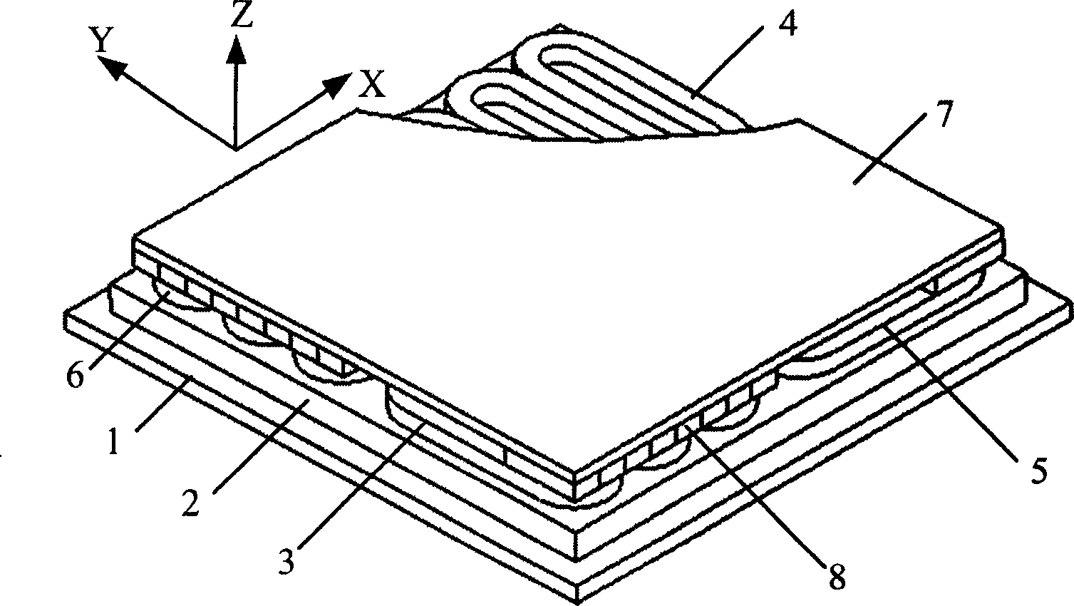
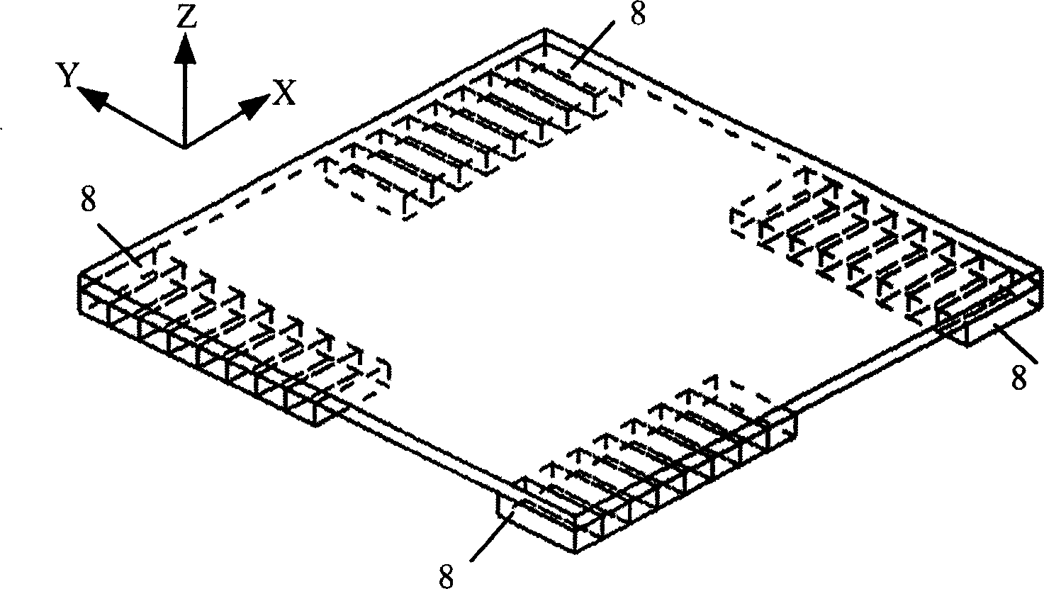
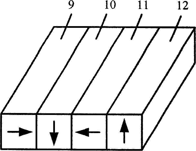
[0015] see figure 1 , 2. The present invention includes a frame 1, a stator core 2 with a smooth surface and no slots arranged on the frame 1, and a mover platform 7 floating on the stator core 2, wherein the frame 1 is used as a base for installing the stator core 2 Seat, the upper surface of the stator core 2 and the lower surface of the mover platform 7 are parallel to each other, and there is a thin air gap between them, and the thrust windings 3, 4 and Y in the X direction are respectively arranged on the stator core 2 To the thrust windings 5, 6, and any effective side of the X-direction thrust winding and any effective side of the Y-direction thrust winding are perpendicular to each other, and four Halbach permanent magnet arrays 8 are also arranged on the lower surface of the mover platform 7 , the pe...


PUM


Abstract

This invention discloses a dynamic magnetic synchronous surface motor including a stator and a rotor, in which, the stator includes a stator core and thrust windings, the upper surface of the core is smooth without slots and has two thrust windings of X direction and two of Y direction set on the surface of the stator core and any effective edge of the X is vertical to any effective edge of the Y direction, the lower surface of the rotor platform is arranged with four same Halback magnetic arrays composed of NdFeB magnet, a three-phase winding structure is applied to the X direction and the Y direction thrust windings to be inlet into the three-phase sine AC current with 120 deg. phase difference.

Description

technical field [0001] The invention relates to a high-speed, high-precision surface motor used for chip lithography positioning, in particular to a moving magnet synchronous surface motor. Background technique [0002] With the continuous development of micro- and nano-technology, high-efficiency and high-precision planar drive devices are increasingly required in the fields of micro-mechanical manufacturing and assembly, precision measurement, ultra-precision processing, integrated circuit chip lithography, and scanning tunneling microscopy. The traditional planar driving device is superimposed by two sets of linear motion conversion mechanisms driven by rotary motors. Due to a series of problems such as friction, backlash, and deformation in the linear motion conversion mechanism, it is difficult for the positioning accuracy and efficiency of the traditional planar drive device to reach a high level. In addition, the traditional planar drive device mostly adopts a stacke...

Claims


Application Information

Patent Timeline
IPC IPC(8): H02K41/03
Inventor 梅雪松郝晓红姜歌东张东升陶涛孙挪刚
Owner XI AN JIAOTONG UNIV
Learn More