Terminal dynamic air blow of individuation air conditioning system

A technology for air supply and air conditioning systems, which is applied in the directions of space heating and ventilation, heating and ventilation control systems, heating and ventilation safety systems, etc. Low-cost, easy-to-achieve effects

Inactive Publication Date: 2006-04-12
TSINGHUA UNIV
View PDF1 Cites 21 Cited by
  • Summary
  • Abstract
  • Description
  • Claims
  • Application Information

AI Technical Summary

Problems solved by technology

It is not only technically difficult to envisage making the environmental p

Method used


Image

  • Terminal dynamic air blow of individuation air conditioning system
  • Terminal dynamic air blow of individuation air conditioning system

Examples


Embodiment Construction

[0013] The technical solution of the present invention will be further described below in conjunction with the accompanying drawings.

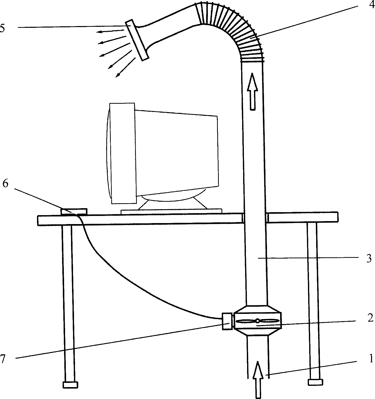
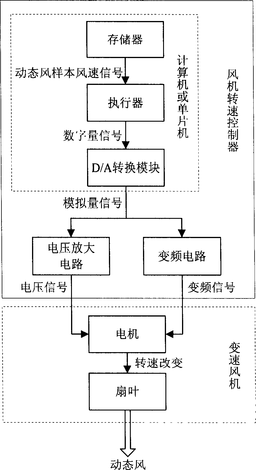
[0014] figure 1 It is a schematic diagram of the appearance and structure of the dynamic air supply device at the operating end of the individual air conditioning system, including the induced air inlet 1, the variable speed fan 2, the air supply pipe section composed of the straight pipe section 3 and the flexible pipe section 4, the diffuse air supply air outlet 5, and the fan The speed controller 7 and the control panel 6 connected to the controller; the fan speed controller 7 includes a computer or a single-chip computer, a voltage amplifier circuit or a frequency conversion circuit; the computer or a single-chip computer contains a storage of natural wind, sine wind, and pulsed wind , Random wind flow dynamic wind sample wind speed signal storage, an actuator that reads the dynamic wind sample wind speed signal from the storage and converts...


PUM


Abstract

A terminal dynamic air supplying unit of personalized air conditioner system is composed of draught port, speed-variable fan, air delivering tube, diffusion-type air supplying port, fan rotation speed controller consisting of computer or single-chip computer, voltage amplifier and frequency converter, and control panel. Said computer has memory, executor and D/A converter. It can supply the dynamic wind similar to natural wind.

Description

Technical field [0001] The invention relates to a terminal air supply device for an individualized air conditioning system, which can generate a dynamic air flow including imitating natural wind. Background technique [0002] For a long time, people have mainly used mixed ventilation air-conditioning methods to control indoor environmental parameters. The fresh air sent in has been polluted by human biological emissions and other pollutants generated in the room before reaching the human breathing zone. The personalized air supply system can deliver clean air to everyone's breathing area, and at the same time, it can realize the independent control of the air supply temperature and the background temperature of the room. It is a healthy, comfortable and energy-saving new air-conditioning air supply method. [0003] The air supply dynamic technology refers to the change of the air flow velocity through the control device to generate the air velocity that changes with time. The air...

Claims


Application Information

Patent Timeline
IPC IPC(8): F24F11/04
CPCY02B30/746Y02B30/70
Inventor 朱颖心周翔李宏军林冠婧欧阳沁陈晓春
Owner TSINGHUA UNIV
Why Eureka
Try Eureka