High pressure gas support flying wheel battery

A flywheel battery and high-pressure gas technology, applied to electrical components, electromechanical devices, electric components, etc., can solve the problems of inability to accurately know the strength and path, high energy consumption of the control system, and difficult control, so as to improve maintainability and reduce Effects on cost, increased efficiency and service life

Inactive Publication Date: 2006-03-22
XI AN JIAOTONG UNIV
View PDF0 Cites 8 Cited by
  • Summary
  • Abstract
  • Description
  • Claims
  • Application Information

AI Technical Summary

Problems solved by technology

[0007] Although the magnetic levitation technology can meet the requirements of high speed, low loss and long life, its cost is high, and the control system itself consumes a lot of energy
Moreover, the electromagnetic bearing system cannot accurately know the intensity and path of the magnetic flux at the bearing air gap, as well as the nonlinearity associated with ferromagnetic materials, including nonlinear permeability and hysteresis; The physical constraints such as the displacement limited by the output voltage saturation rotor, as well as the gyro effect at high speed and the synchronous disturbance caused by the unbalanced rotor, as well as the external asynchronous disturbance acting on the housing, make its control difficult, giving Installation and debugging and system reliability bring a series of problems, which is why magnetic bearings are not widely used

Method used


Image

  • High pressure gas support flying wheel battery
  • High pressure gas support flying wheel battery
  • High pressure gas support flying wheel battery

Examples


Embodiment Construction

[0029] The structural principle and working principle of the present invention will be further described in detail below in conjunction with the accompanying drawings.

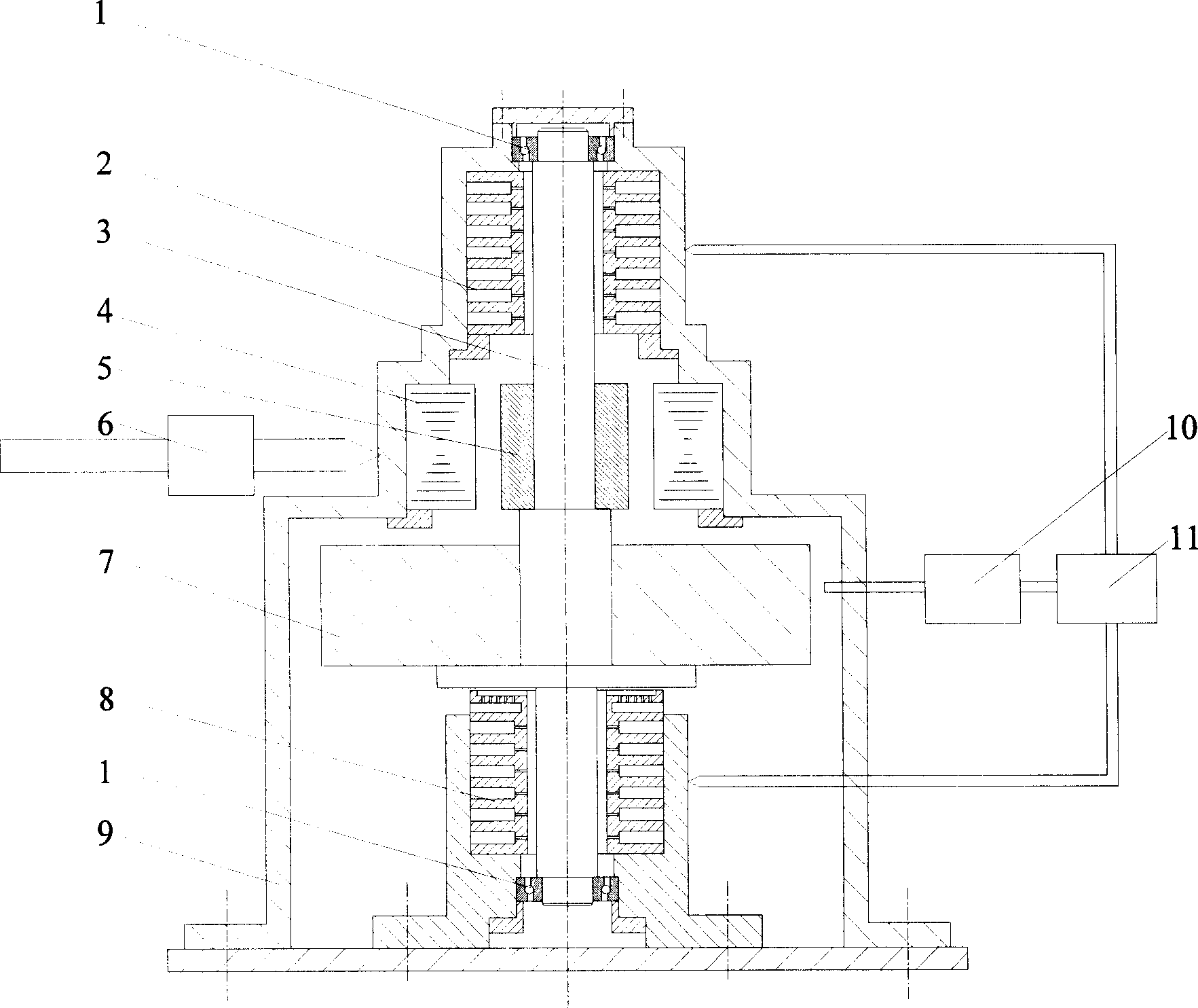
[0030] refer to figure 1 As shown, the energy conversion process of the flywheel energy storage system can be seen from the figure: when charging, the electric energy passes through the power electronic conversion device 6 to drive the motor 17 to drive the flywheel 7 to accelerate the rotation, and the electric energy becomes mechanical energy storage. When discharging, the motor 17 acts as a generator, driven by the flywheel 7 to generate electricity, and the power electronic conversion device 6 outputs electric energy, while the kinetic energy of the flywheel is reduced.

[0031] refer to figure 2 As shown, the present invention includes a sealing shield 9, a main shaft 3 is arranged in the center of the sealing shield 9, the upper and lower ends of the main shaft 3 are in interference fit with the inner ...


PUM


Abstract

This invention discloses a high pressure gas supported flywheel cell, which takes a high pressure gas bottle as the gas source to input an inert gas into a gas bearing via a regulator and a filter to float the flywheel. When charging, the power supply drives the motor via a power electronic conversion device to drive the flywheel rotate at high speed and convert the electric energy to dynamic energy to be stored. When discharging, the motor becomes a generator to generate electricity driven by the flywheel to return electric energy to the power supply. The vacuum pump extracts the inert gas from the flywheel sealed protection shade and transports it to the gas source.

Description

technical field [0001] The invention relates to a flywheel energy storage device, in particular to a flywheel energy storage battery supported by high-pressure gas. Background technique [0002] High-speed flywheel energy storage technology is an efficient and cutting-edge new technology, and a green energy storage method, which has attracted extensive attention from various countries. It will play an important role in the future green energy system. From the research situation at home and abroad, the main load-carrying forms of flywheel batteries include mechanical bearing, magnetic bearing, and combined bearing of mechanical bearing and magnetic bearing. [0003] Because mechanical bearings have the characteristics of simple installation and debugging, low cost, mature technology, and high stability, mechanical bearings are often used in early flywheel battery devices. Such bearings include: ceramic bearings, jewel bearings and rolling bearings. Flywheels of this type o...

Claims


Application Information

Patent Timeline
Patent Type & Authority Applications(China)
IPC IPC(8): H02K7/08H02K7/02F16C32/06
CPCY02E60/16
Inventor 康龙云郭振宇张传伟曹秉刚
Owner XI AN JIAOTONG UNIV
Why Eureka
Try Eureka