Blower having a carrying frame

A technology for bearing frames and blowers, which is applied in household appliances, mechanical equipment, machines/engines, etc.

Inactive Publication Date: 2006-03-22
ANDREAS STIHL AG & CO KG
View PDF1 Cites 3 Cited by
  • Summary
  • Abstract
  • Description
  • Claims
  • Application Information

AI Technical Summary

Problems solved by technology

This filter part has to be mounted externally on the blower which is a tricky and complicated job

Method used


Image

  • Blower having a carrying frame
  • Blower having a carrying frame
  • Blower having a carrying frame

Examples


Embodiment Construction

[0015] figure 1 The blower 1 shown in a side view in the middle is a backpack-type blower, and the blower can be fixed on the back of an operator (not shown) through a belt 2. This blower can also be installed on a vehicle or bracket, or used in other ways.

[0016] The blower 1 is fixed on the supporting frame 7. The carrying frame 7 includes a bottom plate 5 and a supporting member 6; the bottom plate 5 and the supporting member 6 are arranged in an L shape with respect to each other, such as figure 1 Shown in a side view of the embodiment described in.

[0017] The blower 1 has a fan comprising a fan cover 4 which is advantageously formed as a fan spiral. The fan is driven by a drive motor 3, which is preferably an internal combustion engine, such as a two-stroke engine or a four-stroke engine.

[0018] The fan (fan cover 4) is fixed to the supporting frame 7 by tightening the screw 17, preferably embodied as a shock absorber. The air inlet 9 of the fan cover 4 faces the bot...


PUM


Abstract

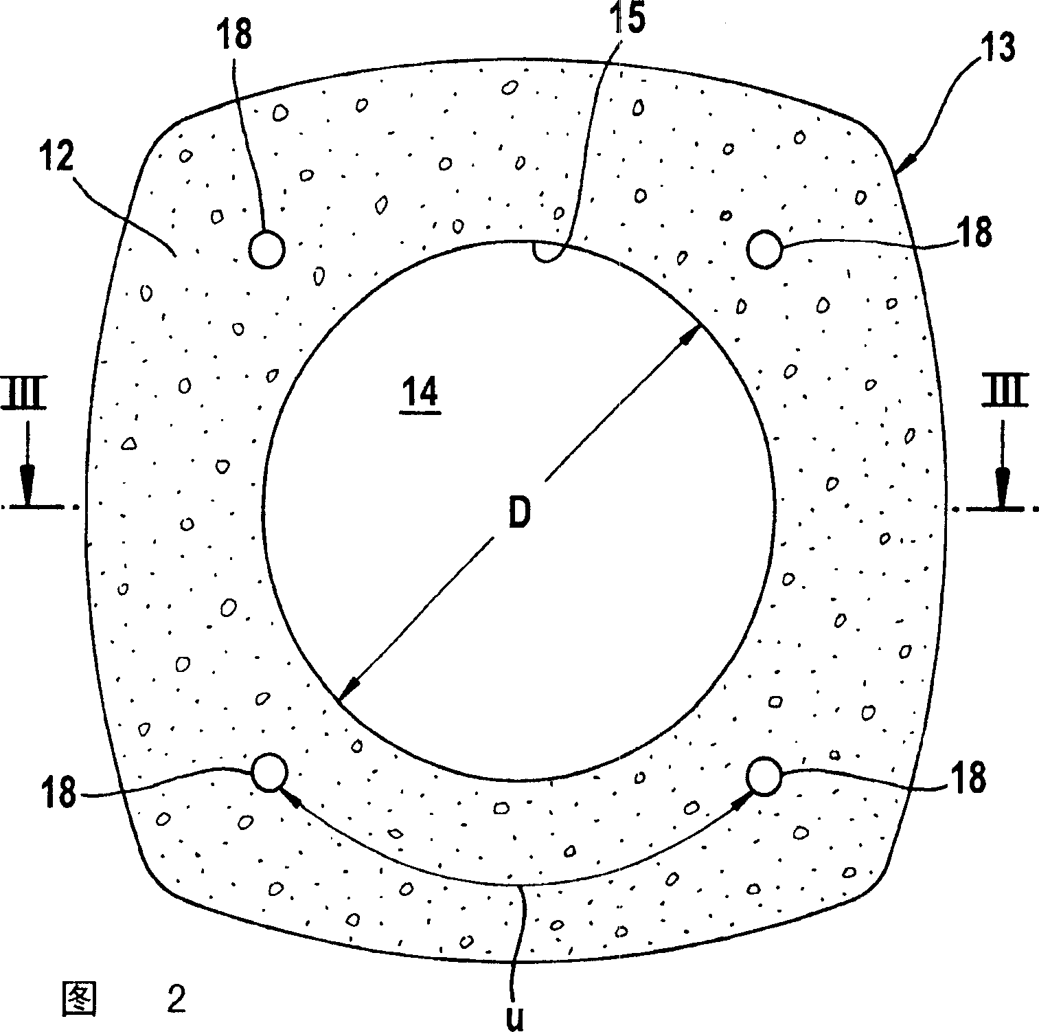
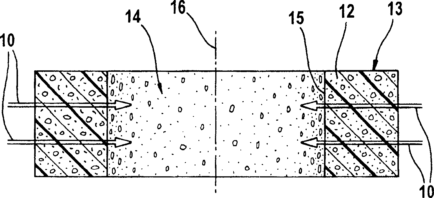
A blower has a load-carrying frame with a base plate. A fan with a fan guard is mounted on the carrier frame. The fan cover has an air inlet facing the base plate and being separated from the base plate. An air intake gap is formed between the bottom plate and the fan case. The internal combustion engine drives a fan so that working air is drawn in through the air intake and blown out through the blower duct. Provide a leaf guard to prevent leaves and debris from entering the fan guard and cover the air intake gap with the leaf guard. The leaf guards are made of coarsely porous foam to allow the entry of operating air unabated and to prevent leaves or other debris from adhering to the leaf guards.

Description

Technical field [0001] The present invention relates to a blower, in particular to a backpack-type blower, which includes a bearing frame with a bottom plate, wherein a fan including a fan cover is installed on the bearing frame. The fan cover has an air inlet, and the air inlet faces the bottom plate and is separated from the bottom plate. In addition, the blower includes an internal combustion engine for driving the fan so as to introduce working air through the intake gap formed between the bottom plate and the fan cover, and blow the working air out through the blower tube. In order to prevent leaves and other debris from entering the fan cover, the air intake gap is covered with a leaf guard. Background technique [0002] Published patent application US2002 / 0174511A1 discloses a blower with an L-shaped load-bearing frame. A fan provided in a fan cover formed as a fan spiral is driven by an internal combustion engine, and the cooling air of the fan is separated from the fan s...

Claims


Application Information

Patent Timeline
Patent Type & Authority Applications(China)
IPC IPC(8): F04D29/70F04D25/02F04D29/02F04D29/60
CPCA47L5/14A01G1/125E01H1/0809A01G20/47
Inventor R·斯卡利J·赫尔拉拉
Owner ANDREAS STIHL AG & CO KG
Why Eureka
Try Eureka