
Optical connector and optical connector module thereof

Pending Publication Date: 2021-12-02
ACSUPER TECH INC
View PDF1 Cites 0 Cited by
  • Summary
  • Abstract
  • Description
  • Claims
  • Application Information

AI Technical Summary

Benefits of technology

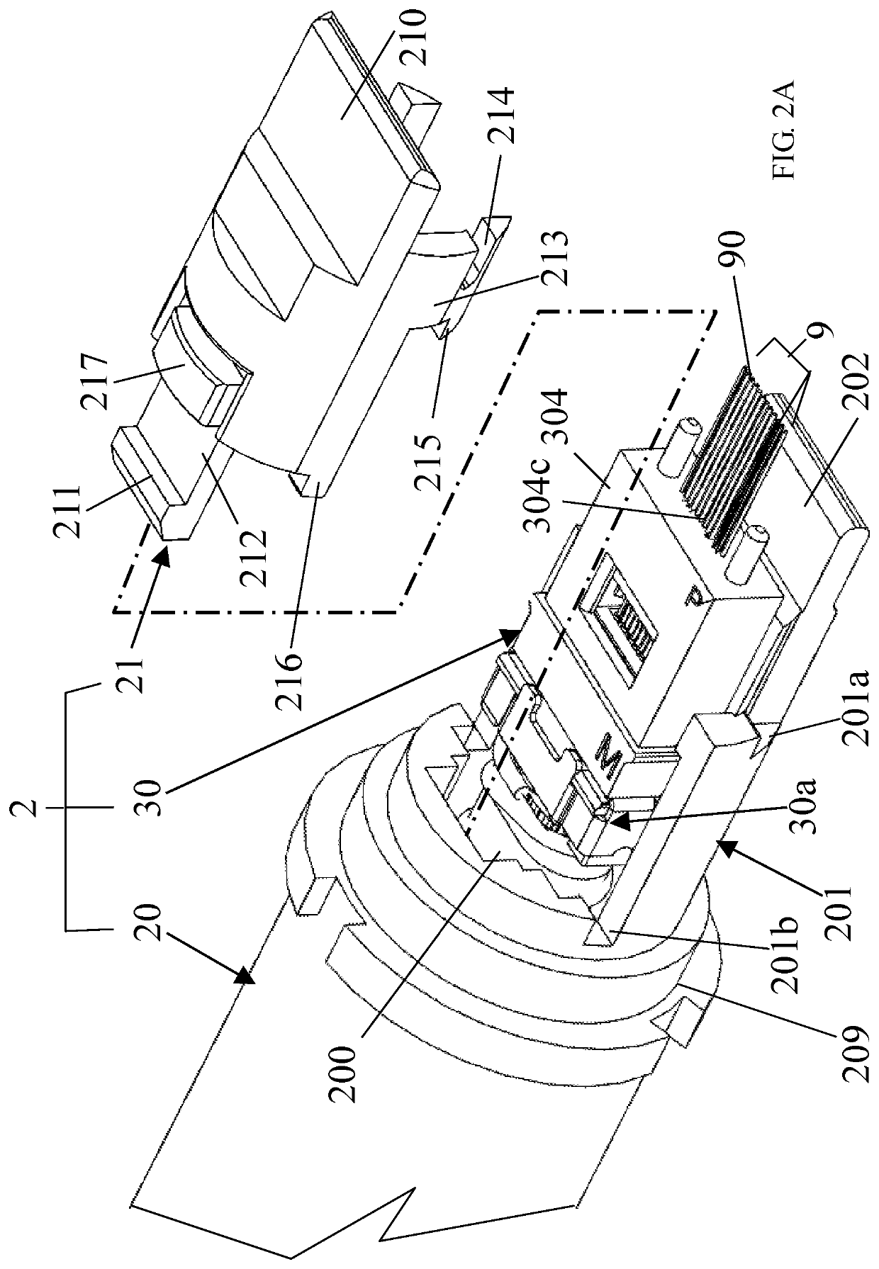
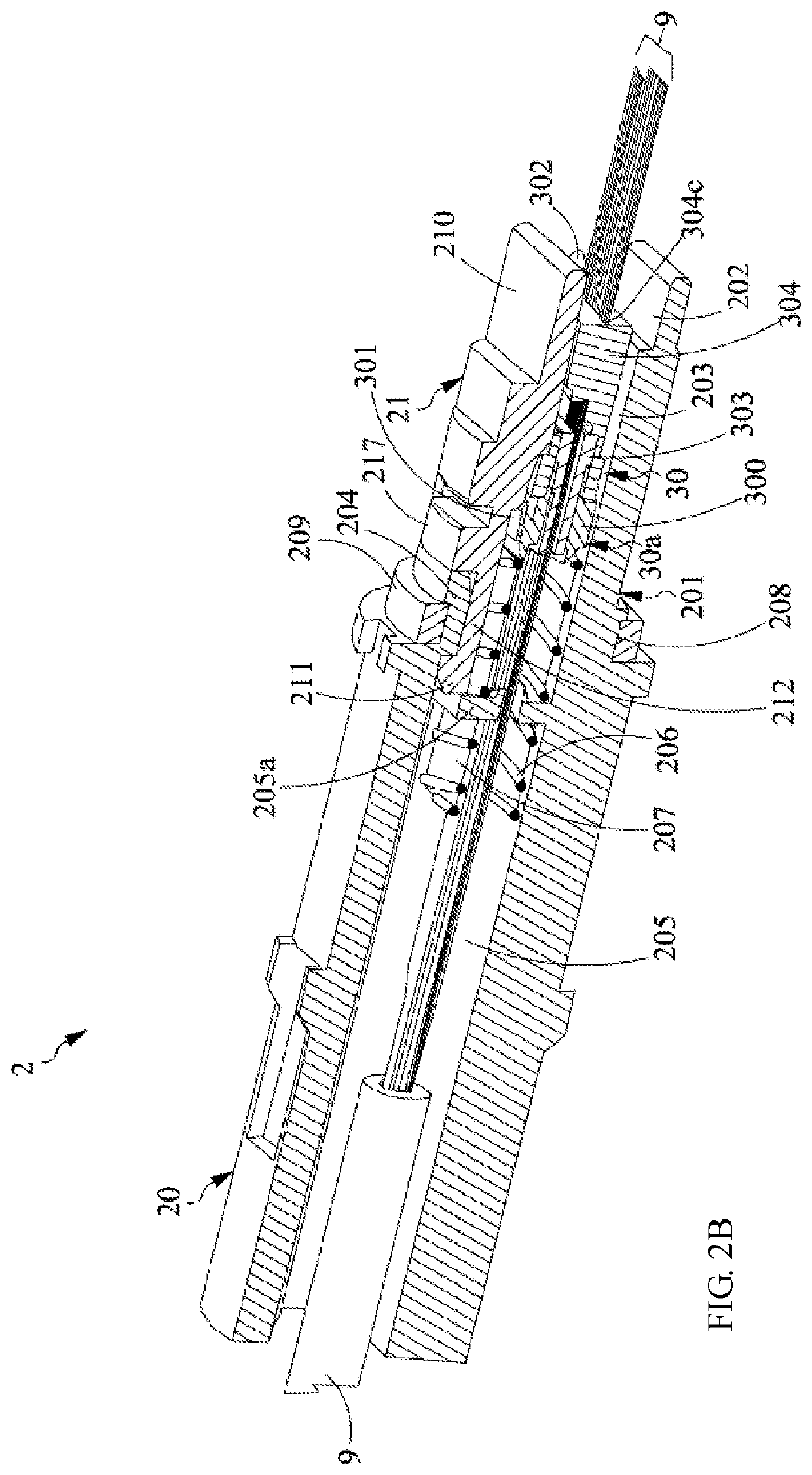
The present invention provides an optical connector with a protection fork that can be used to protect the optical fiber head from pollution and accidental insertion. The protection fork can be easily detached for repair and maintenance of the optical fiber head. The main structure of the optical connector with the optical fiber head can move along the axial direction of the optical connector, which makes it easier to install and maintain the optical fiber head.

Problems solved by technology

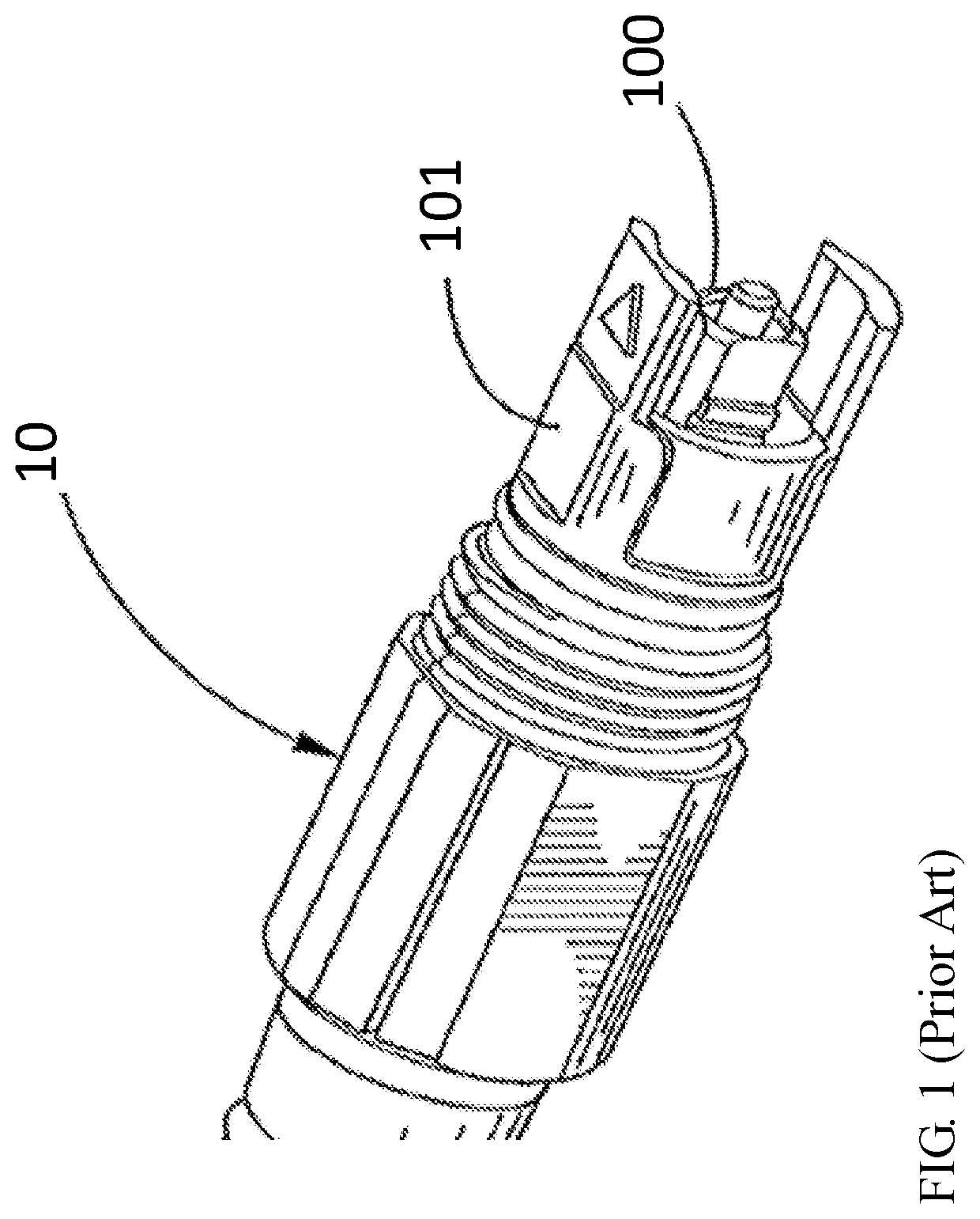
Although this component may protect the optical fiber head 100, it may be very difficult if it needs to be cleaned or checked for contamination.

Method used


Image

  • Optical connector and optical connector module thereof
  • Optical connector and optical connector module thereof
  • Optical connector and optical connector module thereof

Examples


Embodiment Construction

[0024]Reference will now be made in detail to the exemplary embodiments of the present invention, examples of which are illustrated in the accompanying drawings. Therefore, it is to be understood that the foregoing is illustrative of exemplary embodiments and is not to be construed as limited to the specific embodiments disclosed, and that modifications to the disclosed exemplary embodiments, as well as other exemplary embodiments, are intended to be included within the scope of the appended claims. These embodiments are provided so that this invention will be thorough and complete, and will fully convey the inventive concept to those skilled in the art. The relative proportions and ratios of elements in the drawings may be exaggerated or diminished in size for the sake of clarity and convenience in the drawings, and such arbitrary proportions are only illustrative and not limiting in any way.

[0025]For convenience, certain terms employed in the specification, examples and appended c...


PUM


Abstract

The present invention provides a latch structure arranged in an optical receptacle. The latch structure comprises a supporting element and a first clip structure, wherein the supporting element is assembled with the housing of the optical receptacle. The first clip structure is formed on the supporting element for retaining the optical connector inserting into the optical receptacle. The main idea of the present invention is that when the latch structure assembling with the optical receptacle, there is no interaction force between the first clip structure and optical receptacle so as to maintain the clipping force of the first clip structure acting on the optical connector.

Description

CROSS-REFERENCE TO RELATED APPLICATION[0001]This application claims the benefit under 35 U.S.C. § 119(e) to the U.S.[0002]provisional patent application having the Ser. No. 63 / 032,630 filed on May 31, 2020, the entirety of which is incorporated herein by reference.FIELD OF INVENTION[0003]The present invention relates to an optical connector. In particular, it relates to an optical connector and an optical connector thereof having a detachable protection structure.BACKGROUND OF THE INVENTION[0004]With the increase in communication demand and technological advancement, data centers need better signal transmission media to meet the increasing demand for data volume and transmission speed. Among various signal transmission media, due to the advantages of high frequency bandwidth and low loss, optical fibers have been widely used as signal transmission media in recent years. The use of optical fiber has already had a major revolutionary impact in the communications industry. Nowadays, 10...

Claims


Application Information

Patent Timeline
IPC IPC(8): G02B6/38
CPCG02B6/387G02B6/3839G02B6/3882G02B6/3849G02B6/3887G02B6/3883G02B6/3885
Inventor TSENG, CHUNG-MING
Owner ACSUPER TECH INC
Learn More