
Valve, especially radiator valve

A radiator valve and valve seat technology, applied to valves, can solve problems such as large valves

Inactive Publication Date: 2006-03-01
DANFOSS AS
View PDF2 Cites 0 Cited by
  • Summary
  • Abstract
  • Description
  • Claims
  • Application Information

AI Technical Summary

Problems solved by technology

However, this has the consequence that the valves are relatively large

Method used


Image

  • Valve, especially radiator valve
  • Valve, especially radiator valve
  • Valve, especially radiator valve

Examples


Embodiment Construction

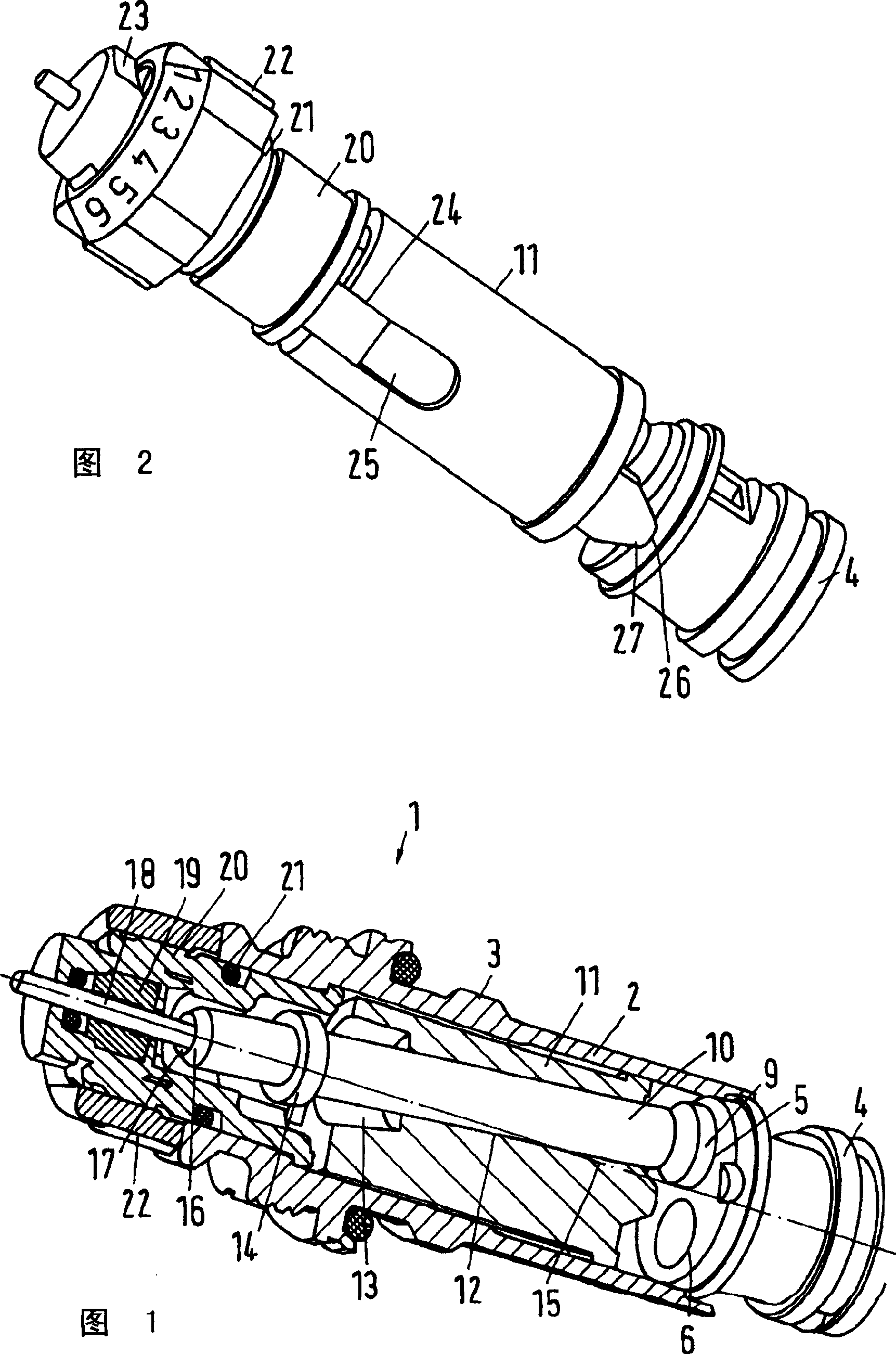
[0027] The radiator valve 1 has a housing 2 which has an external thread 3 by means of which the radiator valve can be screwed onto a radiator not shown in detail. Correspondingly, the radiator valve 1 is made into a built-in valve.

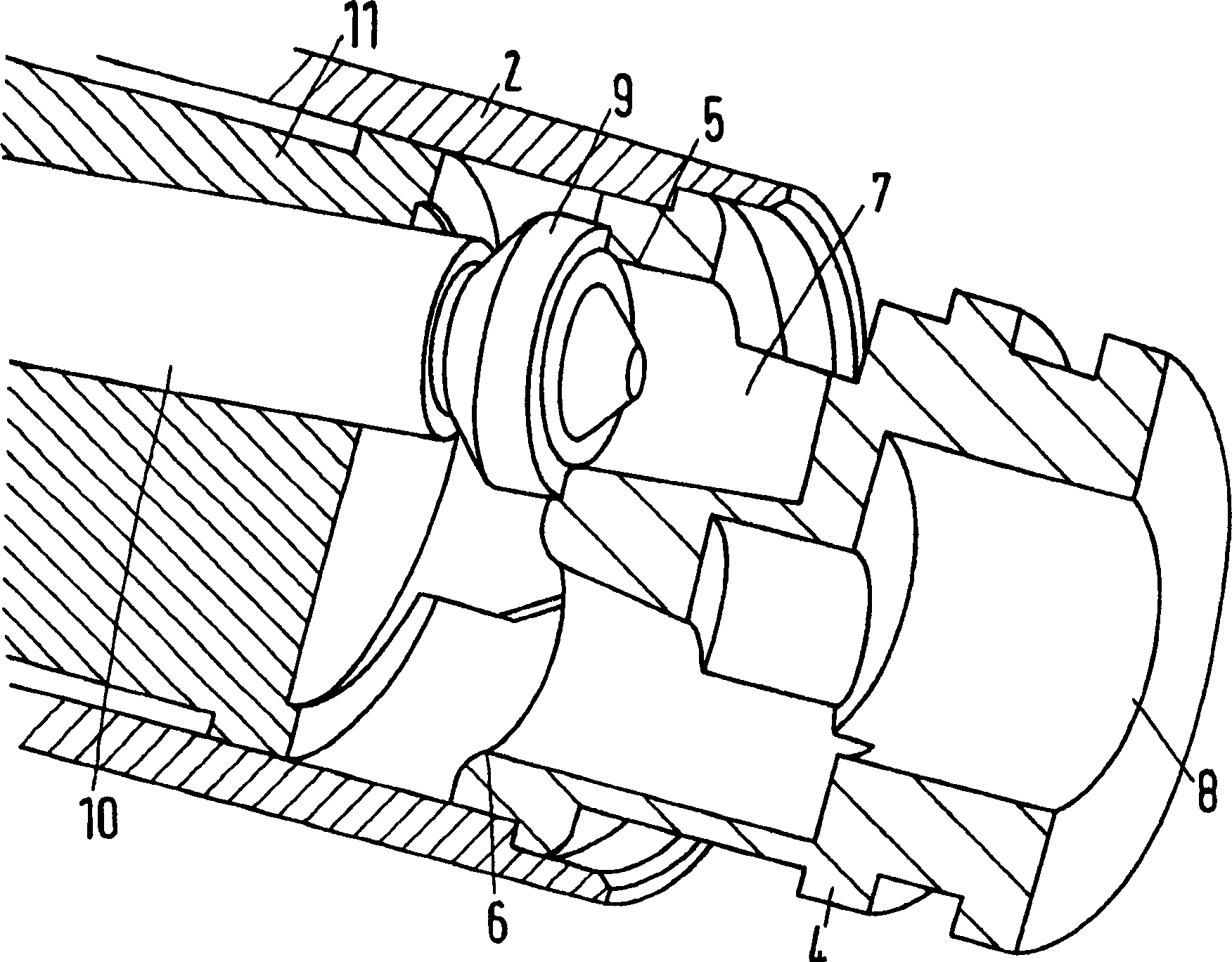
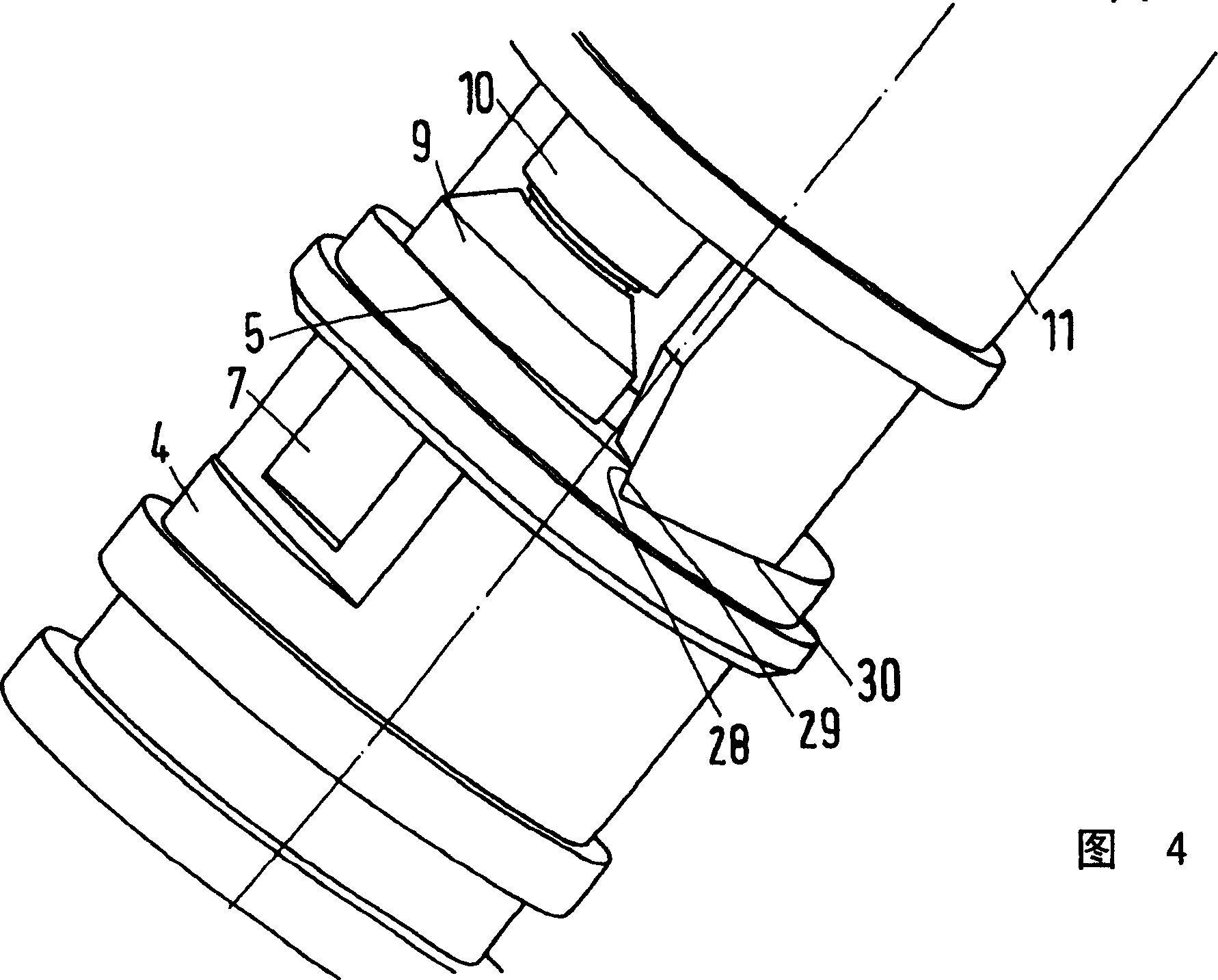
[0028] The housing 2 is connected to a valve seat housing 4 which has a first valve seat 5 and a second valve seat 6 . as from image 3 It can be seen that the first valve seat 5 is connected to an opening 7 formed in the peripheral wall of the valve seat housing 4 , while the second valve seat 6 is connected to an opening 8 on the end face.

[0029] A valve element 9 is arranged inside the housing 2 . The valve element 9 is fixed at one end of the valve stem 10 . The valve rod 10 is supported in a guide 11 which has a guide channel 12 . The guide channel 12 guides the valve stem 10 over most of its length. At the end of the guide channel 12 remote from the valve seat housing 4, the guide channel 12 widens into a recess 13, wherein a spring i...


PUM


Abstract

A valve, especially a radiator valve, has a valve element installed on spindle and a valve seat housing. The latter has a first seat of valve and a second seat of valve. The valve element is installed for displacement between first working position and second working position. In first working position the valve element engages with thefirst seat, and in second working position, with the second seat. A valve spindle which is angled about a predetermined angle opposite a central axis of the valve seat housing. Thereby overall dimensions of valve and space required for arrangement of such valve is reduced.

Description

technical field [0001] The invention relates to a valve, in particular a radiator valve, having a valve element arranged on a valve stem and a valve seat housing having a first valve seat and a second valve seat; wherein the valve The element can be adjusted relative to one another between a first operating position, in which the valve element interacts with the first valve seat, and a second operating position, in which the valve element interacts with the second valve seat. Background technique [0002] Such a valve is known from DE 100 48 688 A1. [0003] The flow direction is generally predetermined on the radiator valve. This throughflow direction should be observed in order to avoid malfunctions, which can be detected in particular by unusual noises. Fluid should flow across the seat to the valve element. When the direction of flow is not observed and the valve is installed incorrectly, fluid flows from the valve element to the valve seat. When the valve is closed,...

Claims


Application Information

Patent Timeline
IPC IPC(8): F16K1/10
CPCF24D19/1018F16K1/10
Inventor N·比耶加德
Owner DANFOSS AS
Learn More