
Apparatus and method for determining the loading and conveying rate of a bridge loader

A technology of conveying device and loader, which is applied in the direction of loading/unloading, measuring device, transportation and packaging, etc., and can solve problems such as small precision

Inactive Publication Date: 2013-10-09
申克加工有限公司
View PDF4 Cites 0 Cited by
  • Summary
  • Abstract
  • Description
  • Claims
  • Application Information

AI Technical Summary

Problems solved by technology

However, compared with multi-roller conveyor scales, single-roller conveyor scales have less precision in determining the conveying rate and thus the conveyed quantity

Method used


Image

  • Apparatus and method for determining the loading and conveying rate of a bridge loader
  • Apparatus and method for determining the loading and conveying rate of a bridge loader
  • Apparatus and method for determining the loading and conveying rate of a bridge loader

Examples


Embodiment Construction

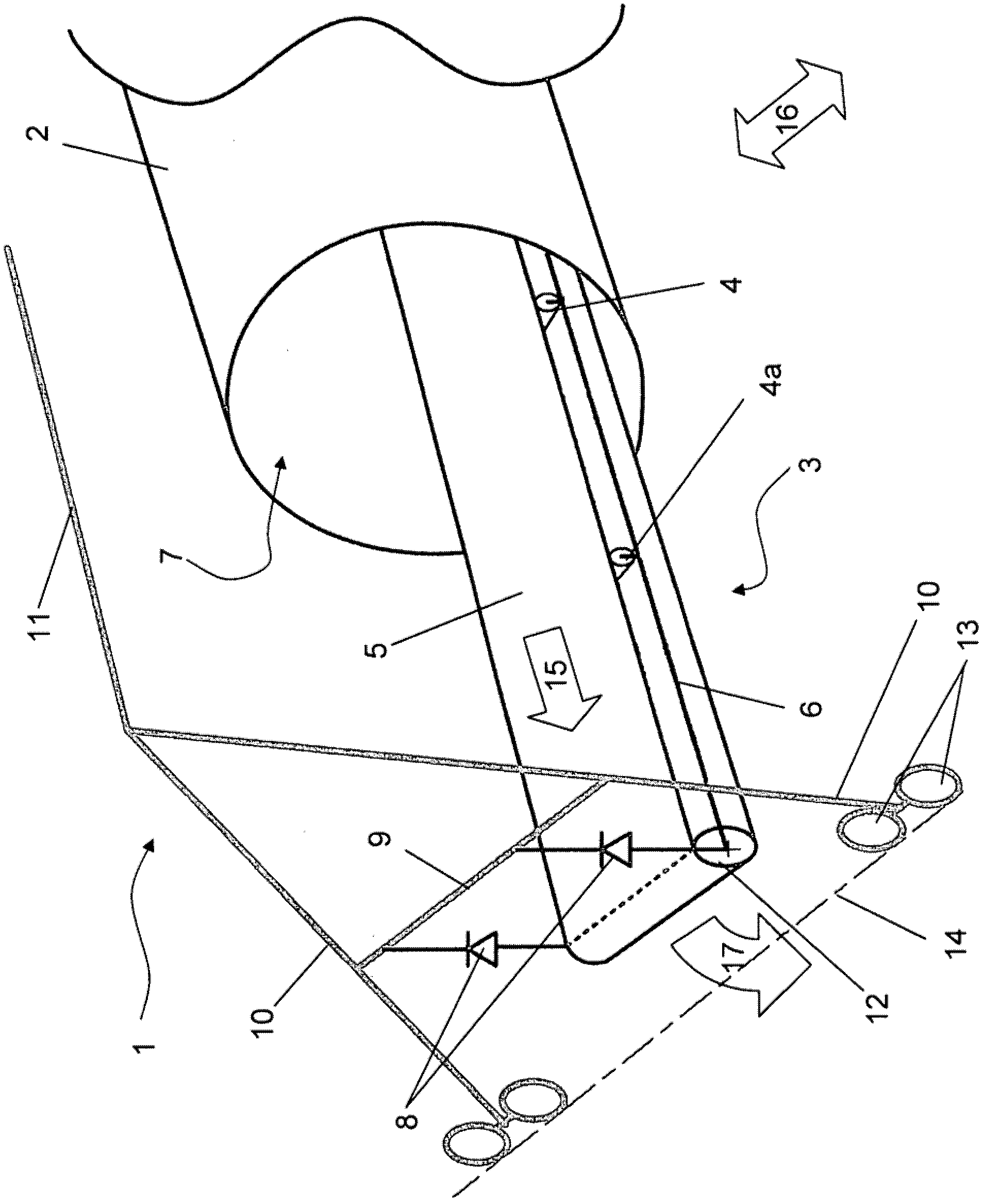
[0036] exist figure 1 shows schematically a part of a bridge loader with a device according to the invention for determining the load delivery rate, where in principle reference can be made to the previous definition of such a bridge loader and determined by This basically avoids repetition in the following description.

[0037] figure 1 A preferred embodiment of a roller bridge loader is shown in . The roller loader 1 comprises a rotary loading tool 2 rotatable about its horizontal axis, which is designed in the form of a loading feed roller, or simply a transfer roller. The diameter of such conveying scald is usually between 5 m and 6 m, for example, but can also be larger or smaller. The conveyor drum has a length which in turn defines the width of the mixed bed pile which can be loaded by it, onto which at least one loose material is poured. Typical lengths may span, for example, a 25 m to 45 m wide mixed bed stock, wherein such a mixed bed stock is not shown in the dr...


PUM


Abstract

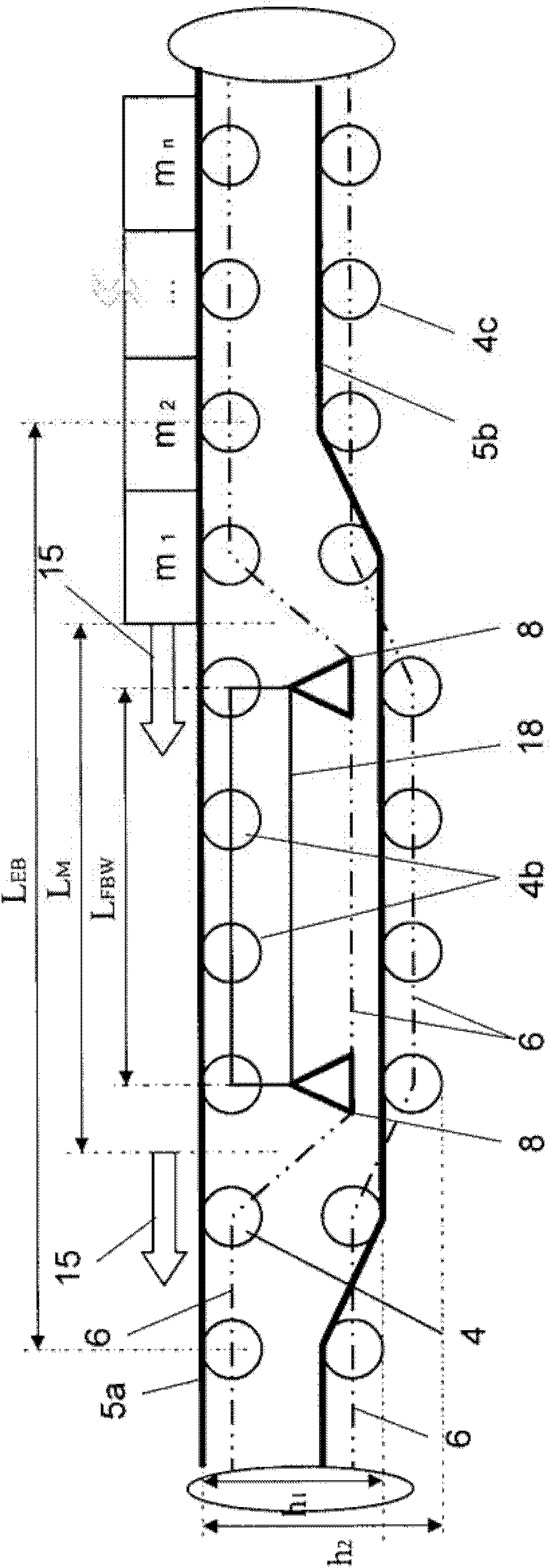
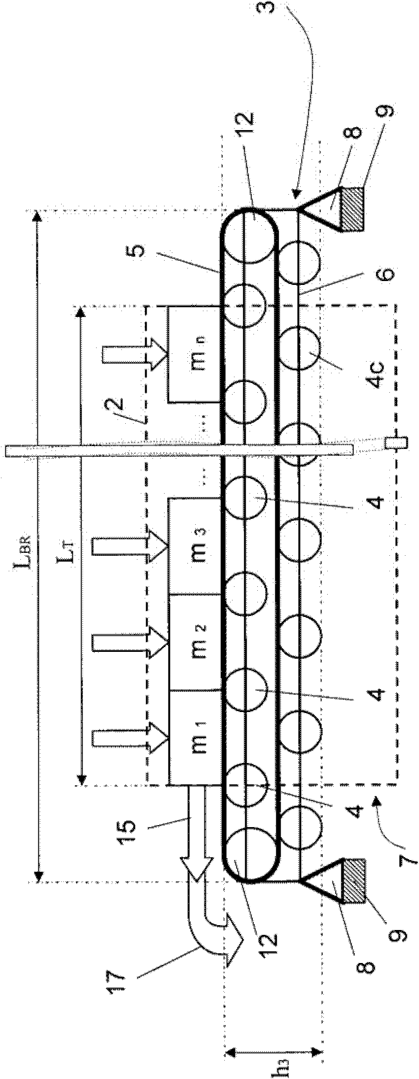
The invention relates to a method and to an apparatus for determining the clearing conveying rate of a bridge clearer (1), spanning a bulk material dump at least partially for clearing the same, and comprising a clearing rotary tool (2) and a conveying device (3). The clearing rotary tool (2) is designed so as to rotate about a horizontal axis, to pick up bulk material from the bulk material dump and to release the same toward the rotation axis. The conveying device (3) comprises a continuous conveyor belt (5) supported by conveyor rollers (4) and a belt frame (6) supporting the conveyor rollers, wherein the conveying device runs substantially alongside the rotation axis of the clearing rotary tool, and wherein the conveying device (3) is guided by the rotary clearing tool such that it is able to pick up the released bulk material and convey it to one of the faces (7) of the rotatable clearing rotary tool (2) of the bridge clearer (1). The invention is characterized in that the conveying device (3) of the bridge clearer (1) is suspended solely via load cells (8) at two opposing first support structures (9) outside of the rotatable clearing rotary tool (2) and forms a conveyor belt balance, the measuring track of which corresponds substantially to the conveying track of the conveying device (3).

Description

technical field [0001] The invention relates to a device and a method for determining or detecting the loading delivery rate of (storage yard) bridge loaders for loose materials, and thus also for determining or detecting bridge loaders, in particular is the delivery capacity of the drum loader (also called "drum reclaimer" in English). Background technique [0002] In order to achieve an optimum material flow in industrial processing procedures, e.g. in sintering plants, power plants or in the manufacture of steel in steelworks, it is often necessary to store bulk quantities of bulk materials to be processed, such as coal, ore, etc. mix them with each other. In order to store raw materials in corresponding blocks, single-component or multi-component material storage (Halde) storage or mixed bed material storage is formed. The stockpile or mixed bed stockpile is filled with an automatically controlled belt stacker ("Stacker" in English) connected to a conveying system, for...

Claims


Application Information

Patent Timeline
Patent Type & Authority Patents(China)
IPC IPC(8): G01G11/00B65G65/20
CPCG01G11/003
Inventor R·施内尔巴彻尔A·鲍文斯
Owner 申克加工有限公司
Learn More