
Centrifugal type clutch and its assembly method

A technology of centrifugal clutches and clutch housings, applied in clutches, automatic clutches, mechanical equipment, etc., can solve the problems that abnormal noise cannot obtain outstanding effects, and the radial displacement of clutch housings cannot be fully suppressed, so as to prevent abnormal noise, Effects of suppressing abnormal noise and suppressing radial displacement

Active Publication Date: 2006-02-22
YAMAHA MOTOR CO LTD
View PDF0 Cites 4 Cited by
  • Summary
  • Abstract
  • Description
  • Claims
  • Application Information

AI Technical Summary

Problems solved by technology

[0008] However, in the housing vibration suppression structure disclosed in Patent Document 1, the aforementioned Image 6 (A) and Image 6 The radial displacement of the vibration belly of the clutch housing shown in (B) cannot be sufficiently suppressed, so that an outstanding effect in suppressing abnormal noise cannot be obtained

Method used


Image

  • Centrifugal type clutch and its assembly method
  • Centrifugal type clutch and its assembly method
  • Centrifugal type clutch and its assembly method

Examples


Embodiment Construction

[0053] Preferred embodiments of the present invention will be described below with reference to the accompanying drawings. However, this description is illustrative in all respects and not restrictive. It should be understood that various changes and modifications can be made without departing from the scope of the invention.

[0054] Figure 10 It is a side view of a motorcycle (a scooter in this embodiment) used as a typical example of a vehicle equipped with the centrifugal clutch of this embodiment.

[0055] Such as Figure 10 As shown, the motorcycle 100 of the present embodiment generally includes: a front fork 101 pivoted on the vehicle frame; a front wheel 102 connected to the lower end of the front fork 101; a steering handle 103 connected to the upper end of the front fork 101; The vehicle seat 104 on the top of the vehicle frame; the engine assembly 106 installed below the vehicle seat 104; the belt type continuously variable transmission 105 that is connected to...


PUM


Abstract

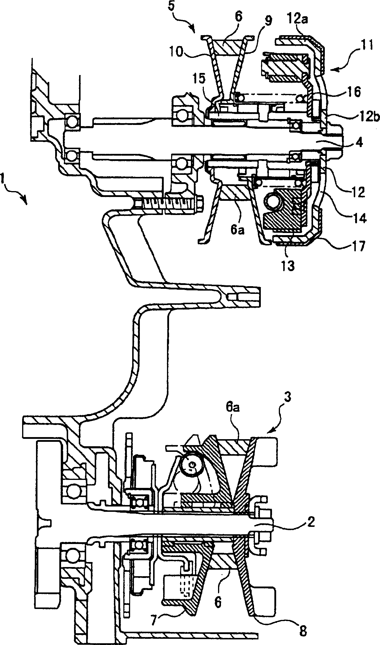
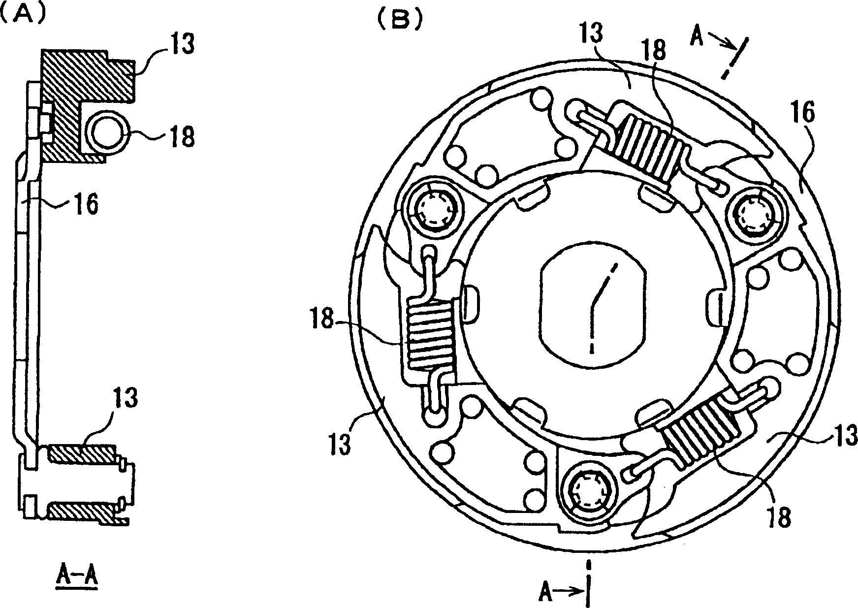
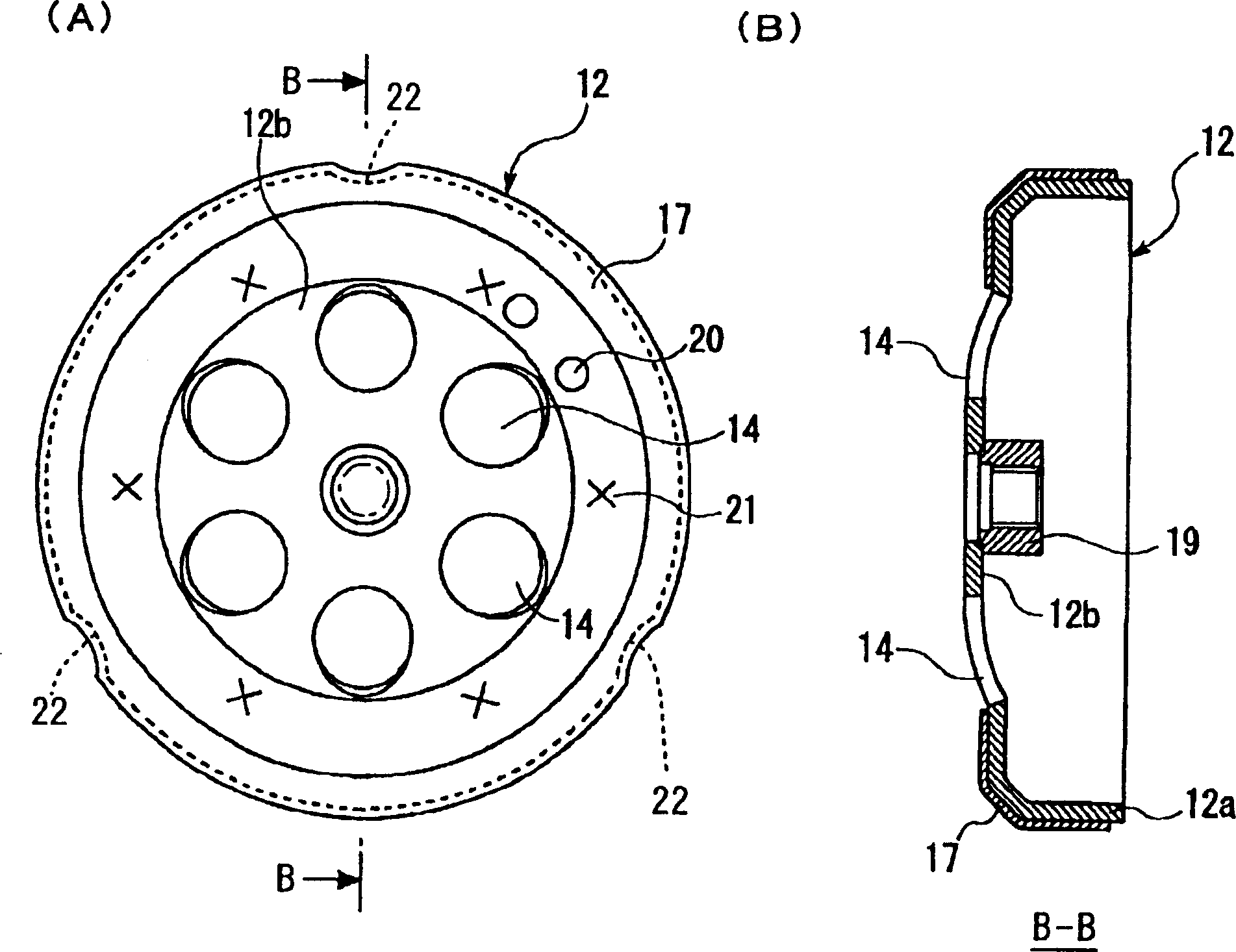
The present invention provides a centrifugal clutch capable of preveting vibration of a cluth housing and effectively preventing ccurrence of abnormal sound. This centrifugal clutch is composed of the clutch housing 12 composed of a circular cylindrical part 12a whose inner face becomes a slide-contact face and a bottom plate part 12b covering one end part of the circular cylindrical part, a rotary shaft which has the same axis as the circular cylindrical part of the clutch housing and to which rotation force is transmitted by the clutch housing, a centrifugal shoe for connecting with the clutch housing 12 or disconnecting from it by rotating around the rotary shaft and coming into contact with or leaving the slide-contact face, and a vibration control cover 17 put on an outer side of the circular cylindrical part. The clutch housing 12 and the vibration control cover 17 have contact parts 30, 40 coming into contact mutually, a non-contact part 50 not in contact, and positioning marks 14, 22 for positioning the clutch housing 12 and the vibration control cover 17 at predetermined relative positions for preventing occurrence of abnormal sound.

Description

technical field [0001] The invention relates to a centrifugal clutch and an assembly method thereof. Background technique [0002] A centrifugal clutch equipped with a motorcycle, etc. is composed of the following parts: a cylindrical part whose inner surface is a sliding surface; a bowl-shaped clutch case composed of a bottom plate part covering one end of the cylindrical part; and a cylindrical part coaxial with the clutch case and a rotating shaft to which torque is transmitted from the clutch housing; and a centrifugal shoe that engages or separates from the clutch housing when contacting or separating from the sliding surface due to the rotation of the rotating shaft. [0003] Such clutches often produce uncomfortable noises as the clutch engages and disengages. One of the causes is the vibration of the cylindrical portion of the clutch housing. [0004] Figure 6 (A) and Figure 6 (B) is a schematic perspective view showing clutch housing vibration. [0005] Circle ...

Claims


Application Information

Patent Timeline
Patent Type & Authority Applications(China)
IPC IPC(8): F16D43/18
Inventor 元胁坚之
Owner YAMAHA MOTOR CO LTD
Learn More