
An interior flow field measurement method for turbomachine

A measurement method, turbomachinery technology, applied in the direction of fluid velocity measurement, measuring device, velocity/acceleration/shock measurement, etc., can solve problems such as interference, inability to measure transient structure, difficulty in measuring internal flow field of multistage turbomachinery, etc. Achieve the effect of avoiding interference and simplifying the structure

Inactive Publication Date: 2006-02-08
BEIHANG UNIV
View PDF0 Cites 17 Cited by
  • Summary
  • Abstract
  • Description
  • Claims
  • Application Information

AI Technical Summary

Problems solved by technology

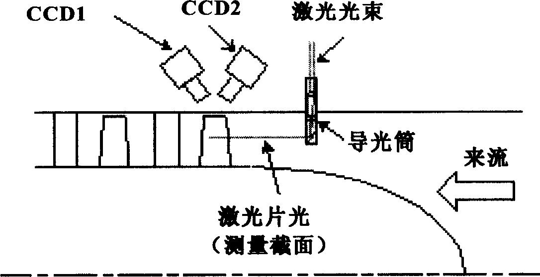
This conventional measurement method has obvious defects in several aspects: it cannot measure the transient structure of the flow field perpendicular to the main flow section, it can only measure a very limited area due to the shielding of the blades, it is more difficult to measure the flow field inside the multi-stage turbomachinery, and the light guide tube Will interfere with the measured flow field

Method used


Image

  • An interior flow field measurement method for turbomachine
  • An interior flow field measurement method for turbomachine
  • An interior flow field measurement method for turbomachine

Examples


Embodiment Construction

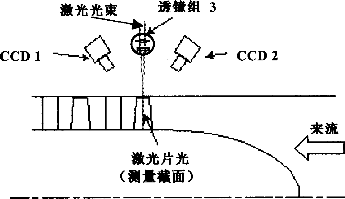
[0018] like figure 2 As shown, the implementation of the present invention does not need to change the SPIV system, only needs to follow figure 2 Lighting, re-arrangement of CCD camera 1, CCD camera 2 and lens group 3 forming laser sheet light in the manner shown is enough, but special calibration and three-dimensional velocity field synthesis should be carried out according to the characteristics of the turbine, and the measurement process and steps are the same as Regular measurements agree exactly.

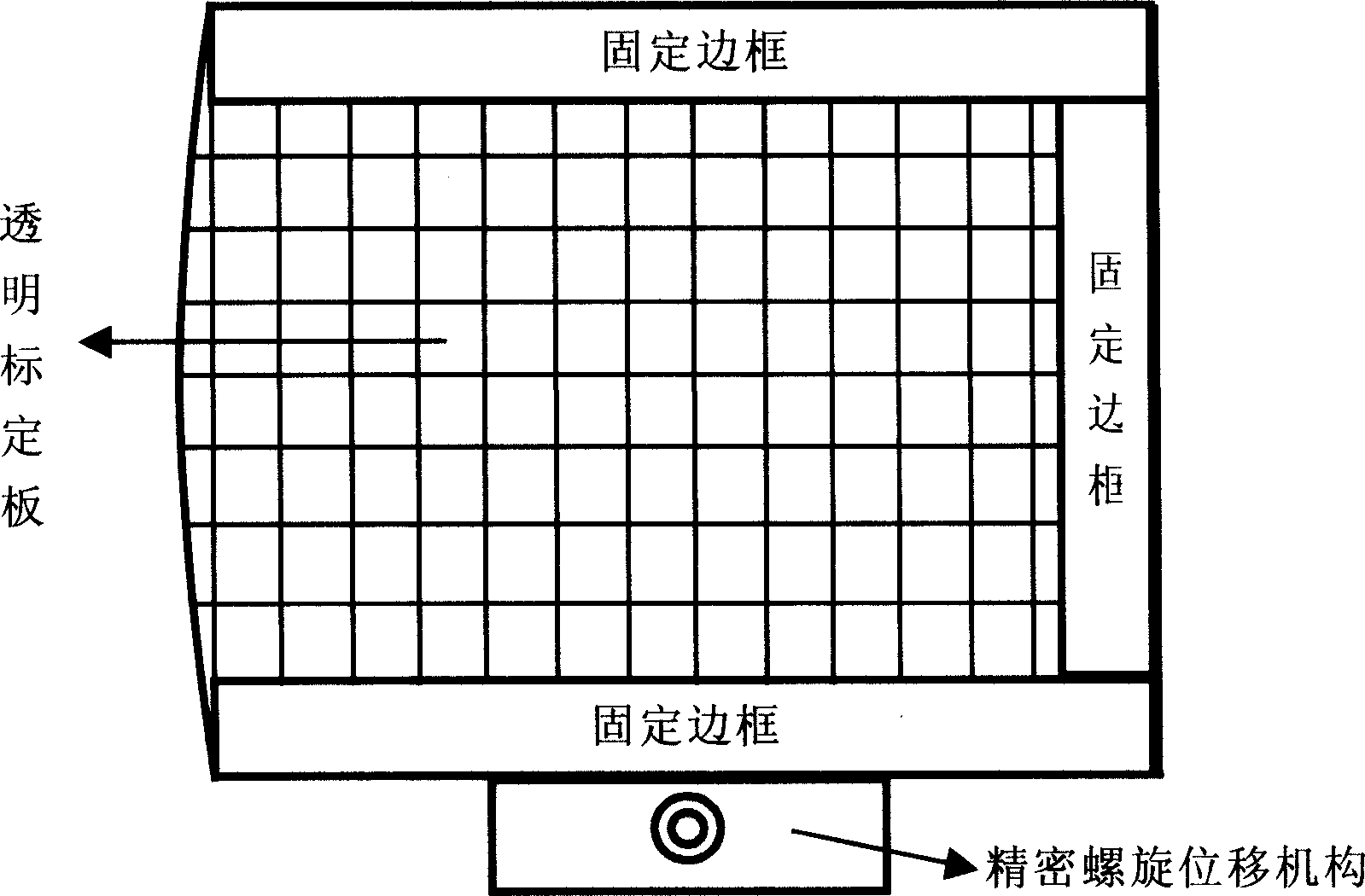
[0019] First, before measuring, it is necessary to use such as image 3 The transparent calibration object shown is used to calibrate the SPIV system. During the calibration process, the receiver window should also be worn, so the side of the transparent calibration object close to the receiver window should be made into an arc, which is consistent with the receiver window; in principle Calibration is required for each of the different measurement positions; the process and...


PUM


Abstract

The invention relates to a turbo-machine internal flow field measuring method, which does not need to change the current SPIV system and only need to displace the laser sheet light and the CCD camera according to the accompany diagram mold, then it dose special calibration and 3-D velocity field composition by the character of the turbine; it is characterized in that it does not need the complex leaded light column and all of the measuring devices are outside the box viewer; the laser sheet light through the box viewer and directly lightens the detected section; two suits CCD camera are separately positioned on the two sides of the laser sheet light so as to measure the box near-wall area. Using the 3-D velocity field composition can obtain high special resolution and large compositing area.

Description

technical field [0001] The invention relates to a method for measuring complex flow problems in a turbomachinery, which is mainly used to solve the problem of measuring the transient velocity field of various flow direction vortices and secondary flows in a single / multi-stage turbomachinery when the particle image velocity measurement technology SPIV is applied . Background technique [0002] my country has purchased a large number of particle image velocity measurement equipment SPIV equipment from abroad, and quite a few of them are in the field of turbomachinery research. At present, the measurement methods at home and abroad are as follows: figure 1 As shown, a sophisticated light guide tube is required to introduce the laser into the flow field to form a sheet of light. The illuminated measurement section is parallel to the direction of the mechanical axis of the impeller, and the two CCD cameras are naturally arranged on the same side of the laser sheet. . This conve...

Claims


Application Information

Patent Timeline
Patent Type & Authority Applications(China)
IPC IPC(8): G01P5/20
Inventor 刘宝杰于贤君刘火星
Owner BEIHANG UNIV
Learn More