
Surface mount coil component

A coil component, surface mount technology, applied in coil manufacturing, transformer/inductor parts, electrical components, etc., can solve problems such as low bonding strength, thermal degradation of the adhesive 26, peeling, etc., to achieve high reliability, Effect of preventing thermal deterioration

Inactive Publication Date: 2006-02-01
TOKO KABUSHIKI KAISHA
View PDF1 Cites 9 Cited by
  • Summary
  • Abstract
  • Description
  • Claims
  • Application Information

AI Technical Summary

Problems solved by technology

[0008] In this case, since the metal plate terminal material is a conductive material with high thermal conductivity, such as phosphor bronze sprayed with Sn-Cn plating, the energy heated by the heater chip 7 is conducted from the joint portion 23 of the metal plate terminal to the adhesive. The fixed part 23b and the mounting part 23c are fixed, so there is a problem that the adhesive 26 for bonding and fixing the ring magnetic core and the metal plate terminal is thermally deteriorated, and the adhesive strength is lowered and peeled off.
Furthermore, due to the heat, there are important problems such as thermal oxidation of the surface of the mounting part of the metal plate terminal connected to the external circuit, and poor solder wetting of the solder on the substrate.

Method used


Image

  • Surface mount coil component
  • Surface mount coil component
  • Surface mount coil component

Examples


Embodiment

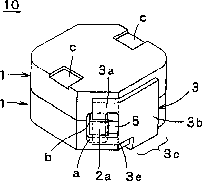
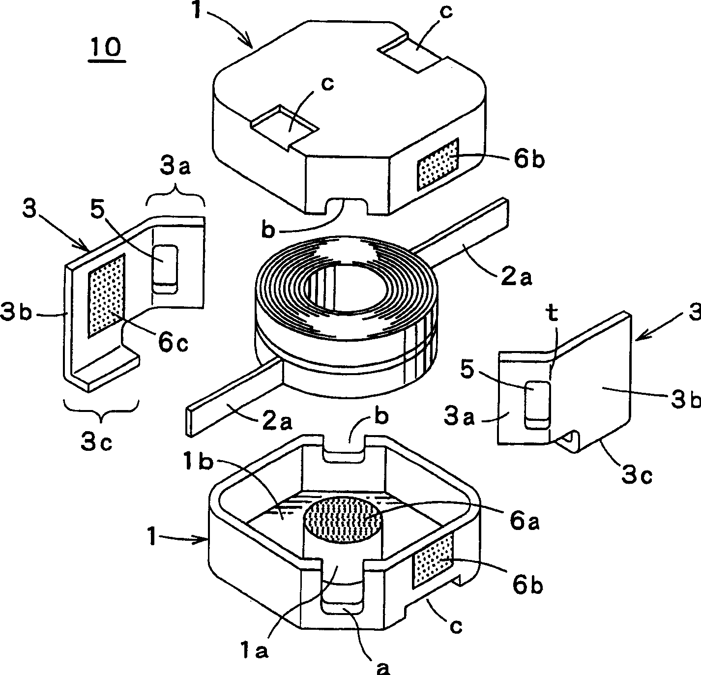
[0032] figure 1 It is a perspective view of the surface mount coil component 10 of the first embodiment of the present invention, figure 2 It is an exploded perspective view of the surface mount coil component 10 of the first embodiment. exist figure 1 and figure 2 Among them, 1 is the magnetic core, 2 is the winding, 2a is the end of the winding, and 3 is the metal plate terminal.

[0033] The winding 2 is an air-core coil formed as a so-called outer-outer winding in which the ends 2a, 2a are drawn out to the outside using a so-called rectangular wire with a square cross-section and an insulating coating on the surface.

[0034] The magnetic core 1 is made of a magnetic body, has a reel 1a in the center, and has a concave portion 1b for accommodating the winding 2, and is formed into an E-shaped substantially quadrangular cross section. A taper is provided on a pair of opposite corners, and notches a and b are provided on the opening of the taper, and holes for allowi...


PUM


Abstract

An object is to provide a highly reliable surface mount coil component quickly and reliably forming thermo-compression bonding on an occasion of thermo-compression bonding by a heater chip, and reliably fixing the metal plate terminal, in a surface mount coil component having thermo-compression bonding of a winding wire and a metal plate terminal. In a surface mount coil component including a winding wire 2, a core 1 and a metal plate terminal 3, the metal plate terminal 3 integrally includes a fixing part 3 b which is bonded and fixed to the core 1, a joint part 3 a to which an end of the winding wire is bonded by thermo-compression bonding, and a mount part 3 c which is connected to an external circuit, the fixing part 3 c is integrally included between the joint part 3 a and the mount part 3 b, and a sectional reduced portion 5 is formed between the joint part 3 a and the fixing part 3 b.

Description

technical field [0001] The present invention relates to a surface mount coil component, and more particularly to a structure of a metal plate terminal connecting the ends of a winding. Background technique [0002] Conventionally, as a coil component used in a small electronic device, for example, it is shown in FIG. 6 . As a top view ( Figure 6A ) and cross-sectional view ( Figure 6B ) shown in the inductor element 40, the drum core 21 made of a magnetic material having the winding core part 21a and the flange parts 21b, 21b provided integrally with it is fixed by the adhesive 27, and the drum core 21 A winding 22 of an insulating coated wire is wound on the winding core portion 21a of the winding core 21, and a cylindrical ring core 24 made of a magnetic material is arranged at intervals on the outer periphery of the drum core 21 on which the winding 22 is wound. [0003] The metal plate terminal 23 extends along the outer surface of the ring core 24 from the bottom su...

Claims


Application Information

Patent Timeline
Patent Type & Authority Applications(China)
IPC IPC(8): H01F27/29H01F27/28H01F17/04
CPCH01F27/2828H01F27/2871H01F2017/046H01F17/043H01F27/292H01F41/10H01F27/28
Inventor 佐佐森邦夫兵头功一郎
Owner TOKO KABUSHIKI KAISHA
Learn More