
Gas discharge lamp

A technology for gas discharge lamps and discharge tubes, which is applied to gas discharge lamps, discharge lamps, and parts of gas discharge lamps, etc., can solve the problems of complicated auxiliary electrode structures and too expensive mass production.

Inactive Publication Date: 2010-12-08
LUMILEDS HLDG BV
View PDF2 Cites 0 Cited by
  • Summary
  • Abstract
  • Description
  • Claims
  • Application Information

AI Technical Summary

Problems solved by technology

The structure of these auxiliary electrodes is usually complex and therefore generally too expensive for mass production

Method used


Image

  • Gas discharge lamp
  • Gas discharge lamp
  • Gas discharge lamp

Examples


Embodiment Construction

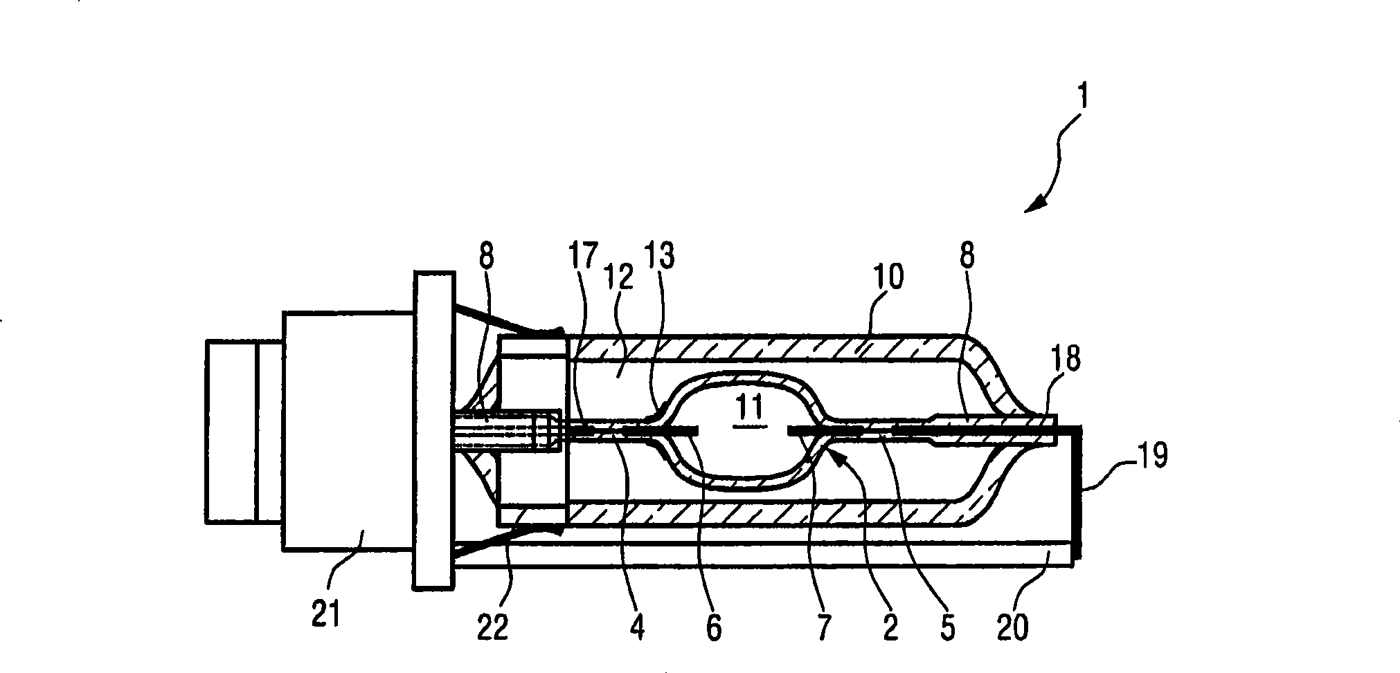
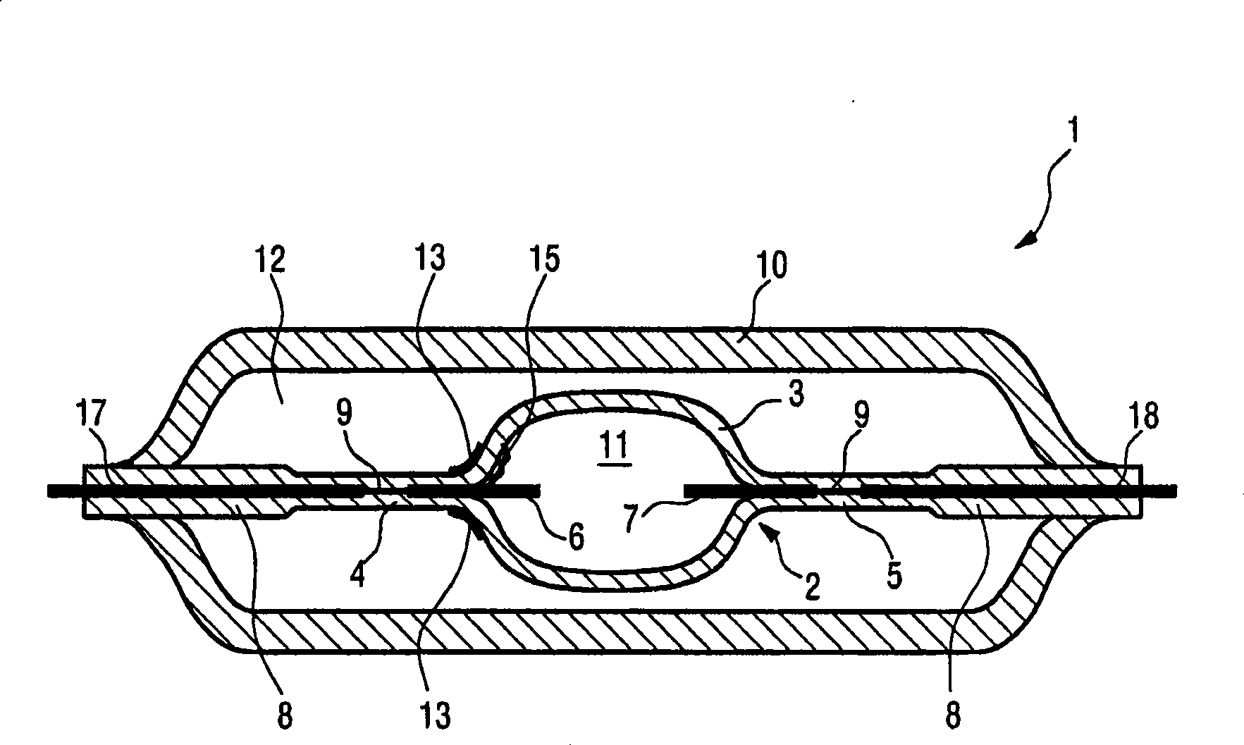
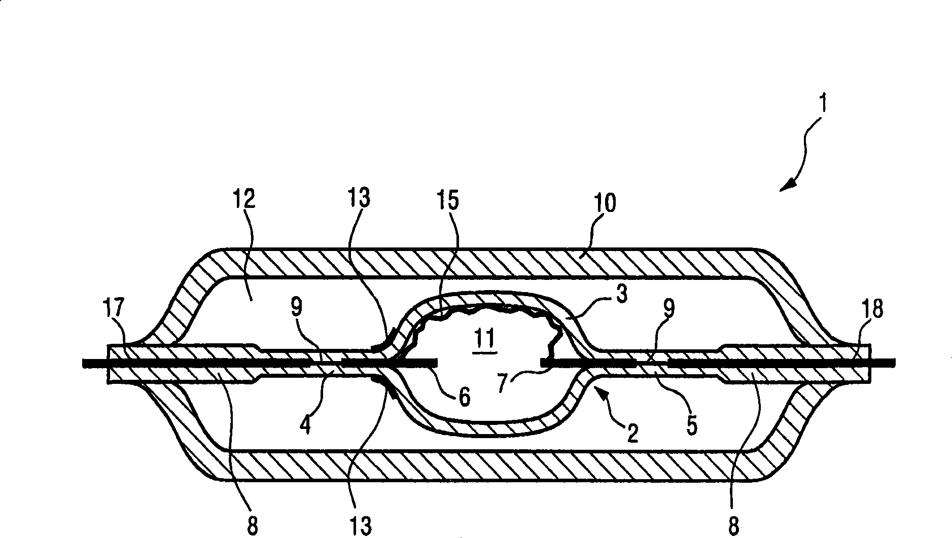
[0032] The embodiment shown in the drawings (not intended to limit the invention) is a preferred MPXL lamp constructed in a conventional manner with an inner bulb 2 and an outer bulb 10 surrounding the inner bulb 2 . The inner bulb 2 here comprises the actual discharge vessel (burner) 3 made of quartz glass with quartz glass end pieces 8 molded onto the discharge vessel 3 on two opposite sides. Immediately adjacent to the discharge vessel 3 , a quartz glass terminal piece 8 is formed as the sealing portion 4 , 5 . Electrodes 6 , 7 protrude from these seals 4 , 5 into discharge vessel 3 . In the sealing part, the electrodes 6, 7 are respectively connected to the thinner and shorter conductive film part 9, wherein the other end of the conductive film part is connected to the power lines 17, 18 respectively. In the region of the sealing parts 4 , 5 , the quartz glass termination pieces 8 are rolled together so that the conductive film part 9 is tightly sealed in the sealing part...


PUM


Abstract

A gas discharge lamp (1) is described. The gas discharge lamp (1) has an inner bulb (2) with a discharge vessel (3) and two sealing sections (4, 5) arranged on the discharge vessel. From the sealing sections (4, 5) electrodes (6, 7) protrude into the discharge vessel (3) each of which are electrically connected with a conductor (9) running in the associated sealing section (4, 5) in order to supply current to the electrodes (6, 7). The gas discharge lamp (1) also has an outer bulb (10) which surrounds the discharge vessel (3) leaving a cavity (12) between the discharge vessel (3) and the outer bulb (10). Close to at least one of the two electrodes (6, 7) in the transitional area between the discharge vessel (3) and the associated sealing section (4, 5) or at a short distance from this transitional area on the outside of the inner bulb (2) is arranged potential-free a conductive structure (13, 13') which on application of a voltage to the electrodes (6, 7) influences the electrical field present in the area of the electrodes (6, 7) concerned such that a discharge arc (15) travels from the electrode (6) concerned first in the direction of a wall section of the discharge vessel (3) adjacent to the electrode and then over the inside of the wall towards the other electrode (7). A method is also described for igniting such a gas discharge lamp (1).

Description

technical field [0001] The invention relates to a gas discharge lamp with an inner bulb and an outer bulb, wherein the inner bulb has a discharge vessel and two seals arranged on the discharge vessel, and two electrodes protruding from the seals towards the discharge vessel, the two The electrodes are respectively electrically connected to the corresponding sealing parts through conductors to supply current to the electrodes, and the outer bulb surrounds the discharge tube, leaving a cavity between the discharge tube and the outer bulb. The invention also relates to a headlamp with such a gas discharge lamp, and to a method for igniting such a gas discharge lamp. Background technique [0002] Gas discharge lamps constructed in the manner described above are usually initially high-pressure gas discharge lamps, such as, for example, high-pressure sodium lamps or in particular MPXL lamps (micropower xenon lamps). In such lamps, the discharge vessel (commonly known as the "burn...

Claims


Application Information

Patent Timeline
Patent Type & Authority Patents(China)
IPC IPC(8): H01J61/54H01J61/10H01J61/34H01J61/35
CPCH01J61/547
Inventor N·勒施M·韦斯特迈耶K·肖勒
Owner LUMILEDS HLDG BV
Learn More