


Quick Research
Generate reliable direction feasibility study reports for your R&D in just a few steps.

Technical Q&A
Discover and master advanced knowledge NOW. Basics, ideas, possibilities, all at once.

Find Solutions
As an expert in R&D theories, this can generate solutions to your technical problems instantly.

Evaluate Feasibility
Analyze your overall solution with one click, know your potential R&D risks in advance.

Monitor Landscape
Get weekly tech updates, stay abreast of the latest tech innovations and key insights.
Electric machine tool
A technology of electric tools and motors, which is applied in the field of receiving bridges, and can solve the problems of increased load at the supporting position
- Summary
- Abstract
- Description
- Claims
- Application Information
AI Technical Summary
Problems solved by technology
Method used
Image

Examples
Embodiment Construction
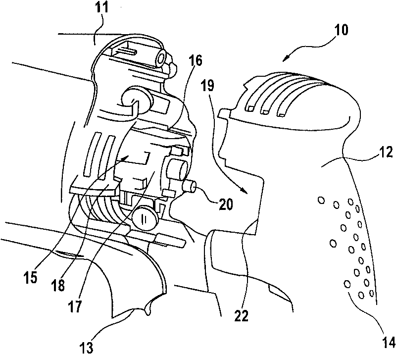
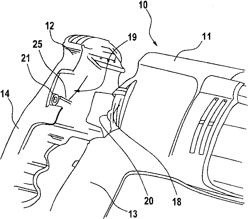
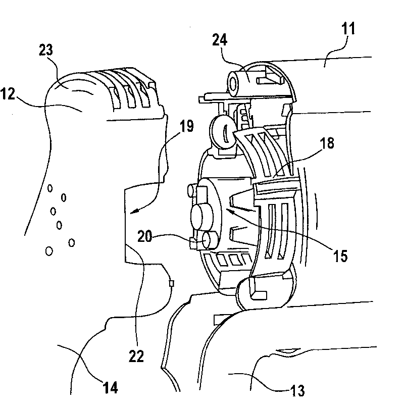
[0018] Figures 1 to 3 shows a preferred electric machine tool 10, which has an electric motor (not shown) arranged in a motor housing 11, at its end on the commutator side, a receiving bridge 15 is provided, one for example overlapping with the electric motor The housing cover 12 which is separated from the motor housing 11 in the various views. The receiving bridge 15 protrudes with its free end from the motor housing 11 into the housing cover 12 . In the region of the free end a rotatable brush plate 16 and a ventilation grid 18 ( figure 1 ).
[0019] For the support of the motor and the receiving bridge 15, support connections 20, 21 are formed between the motor housing 11 and a housing cover 12 which at least partially covers the motor, wherein the housing cover 12 is drawn from the motor housing in the drawing. Body 11 is lifted. The motor housing 11 and the housing cover 12 together form a rear housing part of the electric power tool 10 .
[0020] The housing cover...
PUM
 Abstract
Description
Claims
Application Information
 - R&D Engineer
- R&D Manager
- IP Professional
- Industry Leading Data Capabilities
- Powerful AI technology
- Patent DNA Extraction
Browse by: Latest US Patents, China's latest patents, Technical Efficacy Thesaurus, Application Domain, Technology Topic, Popular Technical Reports.
© 2024 PatSnap. All rights reserved.Legal|Privacy policy|Modern Slavery Act Transparency Statement|Sitemap|About US| Contact US: help@patsnap.com