Magnetic recording medium and magnetic recording and reproducing device
A magnetic recording medium and magnetic recording layer technology, applied in magnetic recording, information recording on disk, data recording, etc., to achieve good flatness, eliminate noise, and inhibit the growth of crystal particles
- Summary
- Abstract
- Description
- Claims
- Application Information
AI Technical Summary
Problems solved by technology
Method used
Image
Examples
example 1
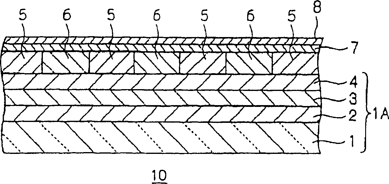
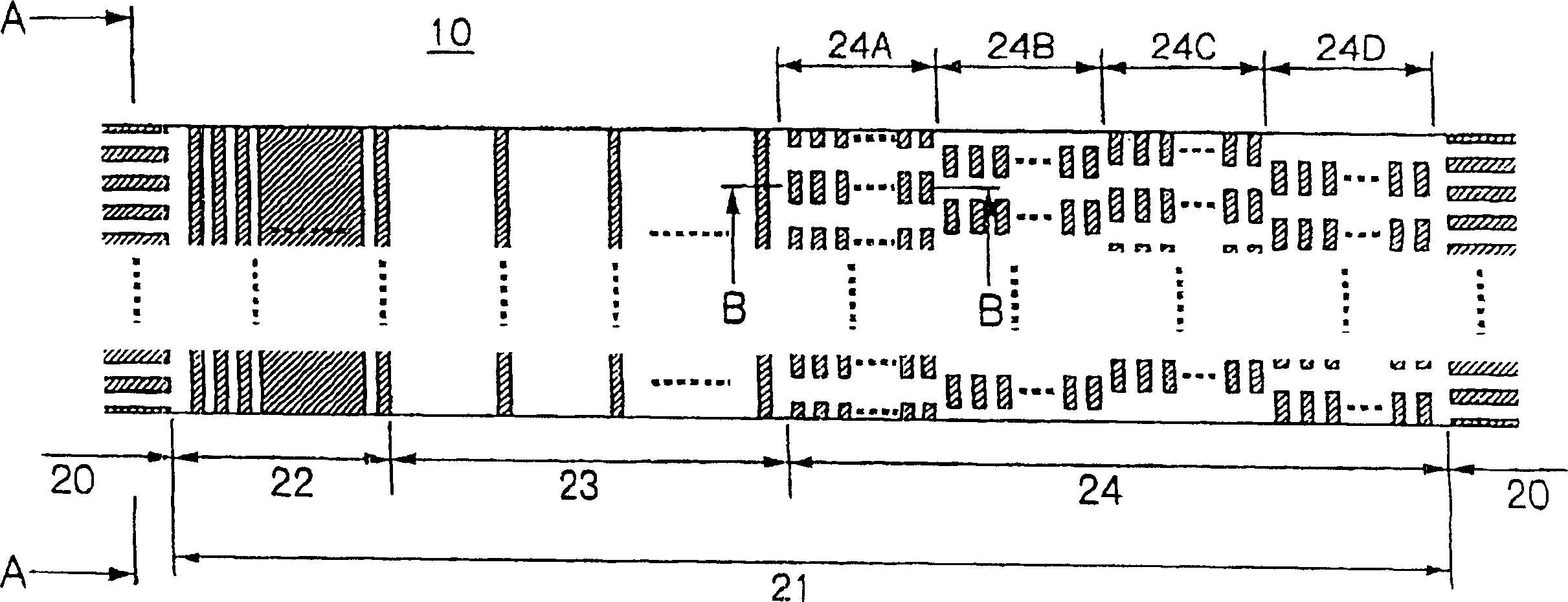
[0110] The non-magnetic layer 6 is formed on the body to be processed obtained as described above. First, under the conditions of 500W film forming power, 150W bias power and 0.3Pa Ar gas pressure, SiO with a thickness of 100nm was formed by sputtering 2 film. Incidentally, the film thickness here means the film thickness when the film is formed in parallel on a flat surface. After the nonmagnetic layer 6 is formed, ion beam etching is performed on the body to be processed with Ar gas and an incident angle of 2 degrees. Like this, eliminate remaining SiO on the magnetic recording layer 5 2 , thereby making the surface flat. Etching was monitored with a mass spectrometer. Once the magnetic recording layer in the data track region 20 starts to be detected, the planarization is complete.
[0111] Incidentally, when the nonmagnetic layer 6 has been formed, the surface position of the nonmagnetic layer 6 in the servo pattern area 21 is lower than that of the nonmagnetic layer ...
example 2
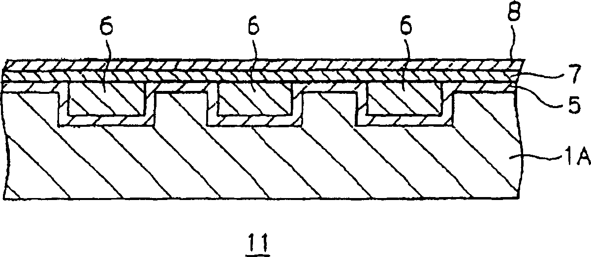
[0118] Figures 4A-4B The manufacturing method of the magnetic recording medium shown is similar to that in Example 1. This magnetic recording medium can be produced as follows. That is, in the ion beam etching of the non-magnetic layer of Example 1, from the start of detection of the magnetic recording layer 5 in each servo pattern area 21 to the start of detection of the magnetic recording layer 5 in each data track area 20, the ions are delayed. beam etching. In this way, planarization is completed.
example 3
[0120] Figures 5A-5B The manufacturing method of the magnetic recording medium shown is similar to that in Example 1. This magnetic recording medium can be produced as follows. That is, in the ion beam etching of the non-magnetic layer of Example 1, once the detection of the magnetic recording layer 5 in each servo pattern area 21 starts, the ion beam etching is suspended. The incident angle is changed from 2 degrees to 90 degrees (90 degrees, because the etching rate of the magnetic recording layer 5 is higher than that of the non-magnetic material (SiO 2 ) etch rate", and then resume the ion beam etching. Once the magnetic recording layer 5 in each data track area 20 starts to be detected, the ion beam etching is suspended. In this way, the planarization is completed.
PUM
| Property | Measurement | Unit |
|---|---|---|
| hardness | aaaaa | aaaaa |
| angle of incidence | aaaaa | aaaaa |
Abstract
Description
Claims
Application Information
 - R&D
- Intellectual Property
- Life Sciences
- Materials
- Tech Scout
- Unparalleled Data Quality
- Higher Quality Content
- 60% Fewer Hallucinations
Browse by: Latest US Patents, China's latest patents, Technical Efficacy Thesaurus, Application Domain, Technology Topic, Popular Technical Reports.
© 2025 PatSnap. All rights reserved.Legal|Privacy policy|Modern Slavery Act Transparency Statement|Sitemap|About US| Contact US: help@patsnap.com


