New type cement soil pile and its construction method
A technology of cement-soil pile and construction method, which is applied in sheet pile wall, foundation structure engineering, sustainable waste treatment, etc., can solve the problem that the mixing pile cannot form a hole, the cement slurry cannot be effectively combined with the foundation soil, and the mixing pile cannot be widely used and other problems to achieve the effect of controlling the coagulation time
- Summary
- Abstract
- Description
- Claims
- Application Information
AI Technical Summary
Problems solved by technology
Method used
Image
Examples
Embodiment 1
[0013] Example 1, a new civil air defense foundation pit support project for an office building is located near the intersection of Guangfu Road and Dianchi Road in Kunming City, between Shili Chang Street and Guangfu Road. The total design area of the proposed building is about 8000m 2 . Frame-shear structure, the buried depth of the basement is -6.1m, partly -5.4m, including a 600mm thick replacement cushion. The surface elevation is ±0.00, partly -0.7m, the pit depth is 6.1m and 5.4m, and the foundation design form is a pile-raft foundation.
[0014] The proposed site is geomorphologically located in the northeast of the Dianchi Basin and belongs to the lacustrine plain geomorphological unit. According to the strata exposed by the 80-meter borehole, and according to the genetic type, sedimentary rhythm, and soil physical and mechanical design parameters, the foundation soil layer is divided into six major layers, which are described from top to bottom as follows:
[00...
Embodiment 2
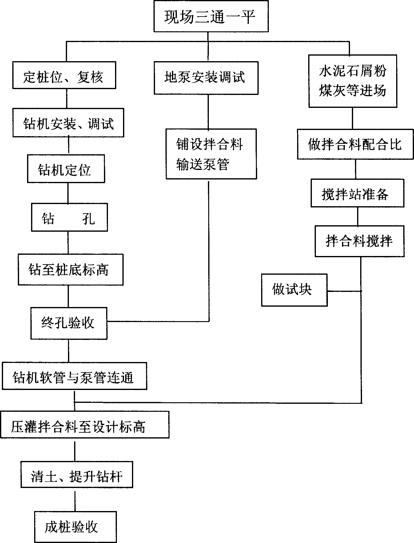
[0034] Example 2, a certain silt soil is 8-11m thick, 4-6m silty clay beneath it, the depth of the foundation pit is 6-7m, and the area of the foundation pit is about 40000m2 2 , using reinforced concrete piles combined with the new cement-soil piles combined soil retaining and water-stop composite support scheme, instead of the original 6-row mixing pile support scheme, can effectively reduce costs, shorten the construction period, and ensure quality. The new cement-soil pile formula (every 1m 3 In water): 350kg of cement, 750kg of good soil, 250kg of stone chips, 75kg of fly ash, 3% of quick-setting agent (weight of cement). The specific gravity of the mixture is required to be 1.3 to 1.5. The above-mentioned process of "forming holes with a long auger drilling machine and pumping new cement-soil mixture into piles in the pipe" is adopted.
Embodiment 3
[0035] Example 3, a quicksand layer with a thickness of about 5-6m, a relatively shallow groundwater depth, and a foundation pit depth of 12m. A composite support scheme for retaining soil and water is adopted that combines reinforced concrete piles with the new cement-soil piles, which can effectively prevent Soil loss between piles ensures the success of foundation pit support. The new cement-soil pile formula (every 1m 3 In water): 300kg of cement, 800kg of good soil, 3% of accelerator (weight of cement). The above-mentioned process of "forming holes with a long auger drilling machine and pumping new cement-soil mixture into piles in the pipe" is adopted.
PUM
| Property | Measurement | Unit |
|---|---|---|
| Resistance | aaaaa | aaaaa |
| Thickness | aaaaa | aaaaa |
| Particle size | aaaaa | aaaaa |
Abstract
Description
Claims
Application Information
 - R&D
- Intellectual Property
- Life Sciences
- Materials
- Tech Scout
- Unparalleled Data Quality
- Higher Quality Content
- 60% Fewer Hallucinations
Browse by: Latest US Patents, China's latest patents, Technical Efficacy Thesaurus, Application Domain, Technology Topic, Popular Technical Reports.
© 2025 PatSnap. All rights reserved.Legal|Privacy policy|Modern Slavery Act Transparency Statement|Sitemap|About US| Contact US: help@patsnap.com

