Cutting saw

A saw machine and frame technology, applied in the field of cutting saws, can solve problems such as too loose or too tight saw blades, low work efficiency, and difficulty in ensuring compliance with requirements

Inactive Publication Date: 2006-01-11
曹新义
View PDF0 Cites 1 Cited by
  • Summary
  • Abstract
  • Description
  • Claims
  • Application Information

AI Technical Summary

Problems solved by technology

The disadvantages of this structure are: 1. Low work efficiency, especially when it takes a long time to replace the saw blade; 2. It is impossible to adjust the saw blade too loose or too tight. Relying on the experience of the staff, it is difficult to guarantee compliance with the requirements

Method used


Image

  • Cutting saw
  • Cutting saw
  • Cutting saw

Examples


Embodiment Construction

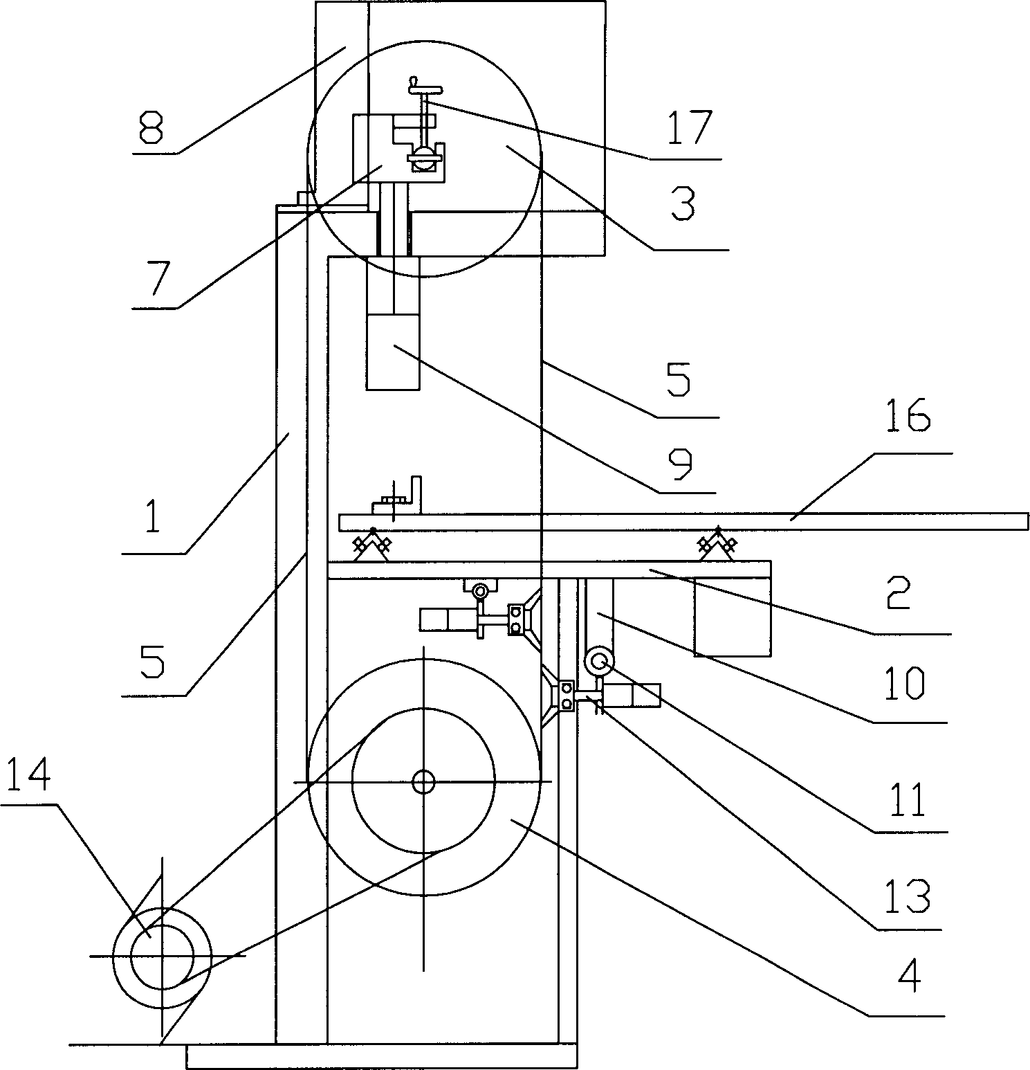
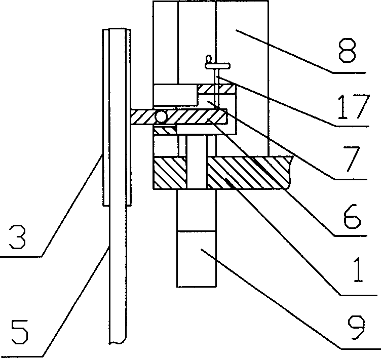
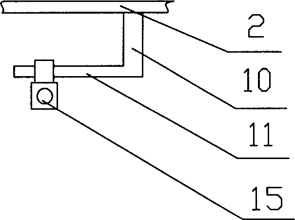
[0018] As shown in the drawings, the cutting saw machine of the present invention includes a frame 1 for supporting various parts; the middle part of the frame 1 has a fixed workbench 2, and a sliding feed plate 16 is placed on the workbench 2 with a pulley During work, the paper roll is placed on the sliding feed plate 16 and sent to the saw blade; the upper end of the frame 1 is equipped with an upper flywheel 3 through the rotating shaft 6; the lower end of the frame 1 is equipped with a lower flywheel 4 connected to the drive motor 14; An annular saw blade 5 is installed between the upper flywheel 3 and the lower flywheel 4; the upper flywheel 3 is installed on the rotating shaft 6, and the rotating shaft 6 is installed on the slide plate 7, and the slide plate 7 is installed in the dovetail groove on the slide plate seat 8, so that the The slide plate seat 8 slides up and down, and the slide plate seat 8 is fixedly installed on the upper end of the frame 1. Sliding plate ...


PUM


Abstract

A sawing machine for cutting paper features that the slide plate pushed by air pump is used to regulate the gap of flywheel for quickly regulating its saw blade and the saw blade is automatically ground by the abrasive disc pushed by said air pump. Its advantages are high productivity and high safety.

Description

technical field [0001] The invention relates to a cutting saw machine, in particular to a cutting saw machine for cutting household paper. Background technique [0002] Toilet paper for daily use needs to be cut into a width of 20-30 centimeters before it can be used conveniently. Manufacturers need to use special equipment—cutting saws—to cut very wide rolls of paper into suitable widths before packaging them for sale. This kind of sawing machine generally has a ring-shaped saw blade hanging from the upper and lower flywheels. Adjusting the axial distance between the upper and lower flywheels can tighten the saw blade. When the flywheel rotates, it will drive the saw blade to move and send it to the workbench. Paper roll cut. The adjustment of the axial distance between the flywheels is generally adjusted in the form of a screw, and the handwheel connected to the screw rotates the screw to cause the displacement of the flywheel connected to the screw. The disadvantages of...

Claims


Application Information

Patent Timeline
IPC IPC(8): B26D1/48B26D7/12
Inventor 曹新义
Owner 曹新义
Why Eureka
Try Eureka