Impressing cylinder protecting device for high-pressrun UV ink-resistance double-layer plate

A protection device and printing resistance technology, which is applied in printing, printing machines, rotary printing machines, etc., can solve the problems of poor shock absorption performance of the protection device of the impression cylinder, affecting the disassembly and assembly of the impression cylinder, etc., so as to facilitate automatic adjustment, The effect of simple structure and easy assembly

Active Publication Date: 2019-08-16
浙江旗创科技集团有限公司
View PDF8 Cites 0 Cited by
  • Summary
  • Abstract
  • Description
  • Claims
  • Application Information

AI Technical Summary

Problems solved by technology

[0005] The object of the present invention is to provide an impression cylinder protection device for a double-layer plate with high printing force and UV ink resistance, so as to solve the problem that the existing impression cylinder protection device proposed in the above background technology affects the disassembly and assembly of the impression cylinder. The problem of poor shock absorption performance of the impression cylinder protection device

Method used


Image

  • Impressing cylinder protecting device for high-pressrun UV ink-resistance double-layer plate
  • Impressing cylinder protecting device for high-pressrun UV ink-resistance double-layer plate
  • Impressing cylinder protecting device for high-pressrun UV ink-resistance double-layer plate

Examples


Embodiment Construction

[0034] The following will clearly and completely describe the technical solutions in the embodiments of the present invention with reference to the accompanying drawings in the embodiments of the present invention. Obviously, the described embodiments are only some, not all, embodiments of the present invention.

[0035] In describing the present invention, it should be understood that the terms "center", "longitudinal", "transverse", "length", "width", "thickness", "upper", "lower", "front", " Back", "Left", "Right", "Vertical", "Horizontal", "Top", "Bottom", "Inner", "Outer", "Clockwise", "Counterclockwise", "Axial" , "radial", "circumferential" and other indicated orientations or positional relationships are based on the orientations or positional relationships shown in the drawings, which are only for the convenience of describing the present invention and simplifying the description, rather than indicating or implying the referred device or Elements must have certain orie...


PUM


Abstract

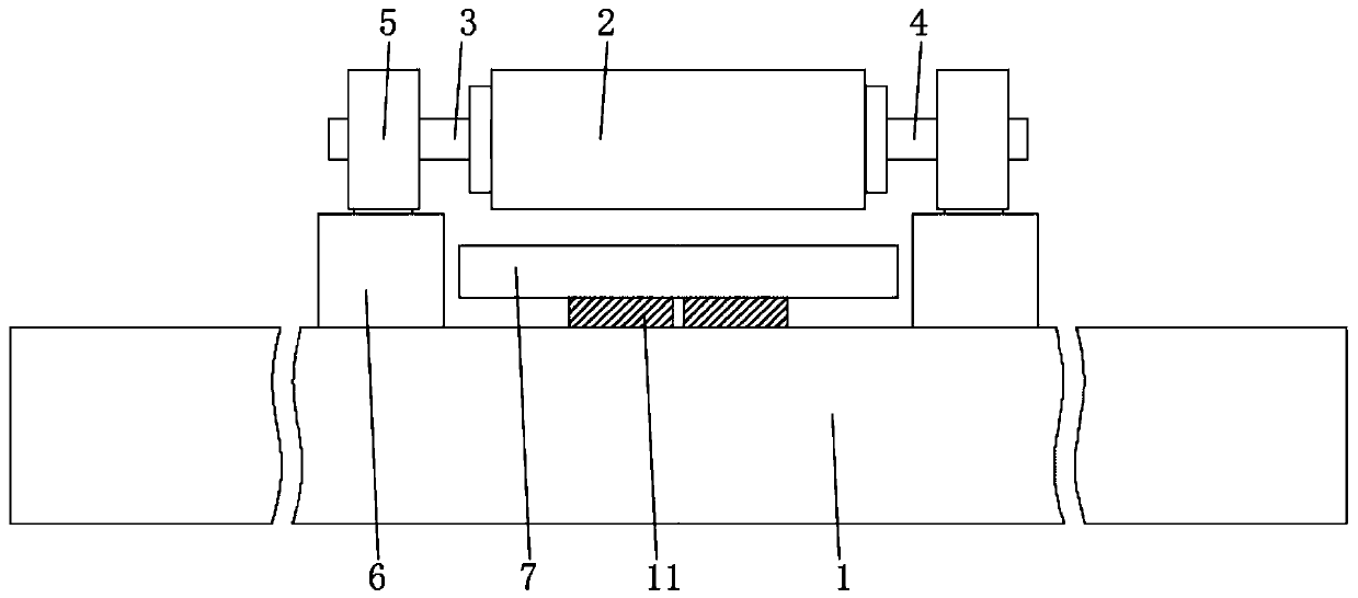
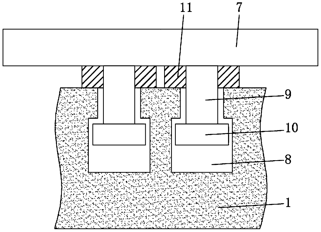
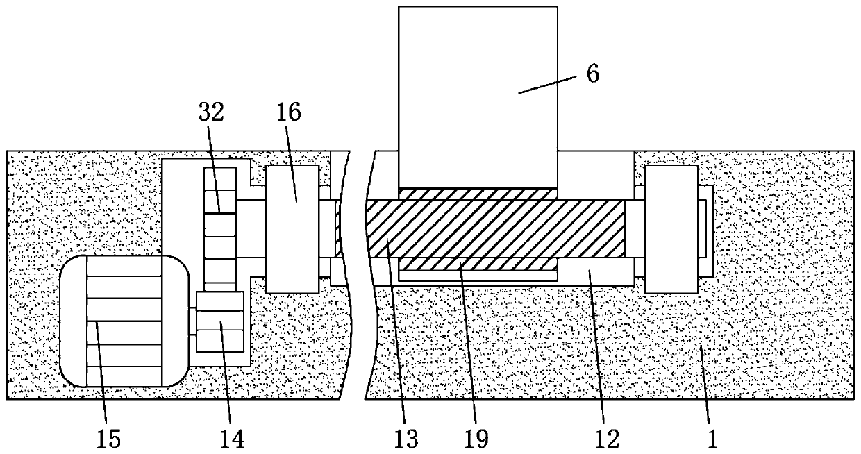
The invention discloses an impressing cylinder protecting device for a high-pressrun UV ink-resistance double-layer plate, and relates to the technical field of offset printing plate machines. The device comprises a base, a protective plate is arranged above the base, an impressing cylinder is arranged above the protective plate, one end of the interior of the impressing cylinder is provided witha first rotating shaft, the other end of the interior of the impressing cylinder is provided with a second rotating shaft, mounting rings are arranged on the outer sides of the first rotating shaft and the second rotating shaft in a sleeving mode, adjusting seats are arranged below the mounting rings respectively, limiting grooves are formed in the middle of the base, the limiting grooves are movably connected with supporting rods, the bottom ends of the supporting rods are fixedly connected with limiting blocks, the top ends of the supporting rods penetrate through the base and are fixedly connected with the protective plate, and first springs sleeve the outer sides of the top ends of the supporting rods. According to the device, the protective plate, the limiting grooves, the supportingrods, the limiting blocks and the first springs are arranged in a matched mode, and can play a role in damping and buffering when the impressing cylinder falls off, so that the impressing cylinder isprevented from being collided and plays a role in protecting the impressing cylinder.

Description

technical field [0001] The invention relates to the technical field of offset printing plate machines, in particular to an embossing cylinder protection device for double-layer plates with high printing force and UV ink resistance. Background technique [0002] CTCP plate is the English abbreviation of Computer To Conventional Plate, which refers to computer direct plate making on the traditional PS plate, as a form of CTP plate process, in fact, CTCP plate is not the next best thing for CTP plate solution, but to complete computer-to-plate and derived another new way. As early as at the drupa1995 International Printing Exposition, Germany Bisheng Graphic Arts Co., Ltd. launched the UV-Setter plate-making machine that has taken shape, demonstrating the new technology of exposing traditional PS offset printing plates using UV light sources. This can be regarded as the first year of the birth of CTCP plates, and it was also at this drupa exhibition that CTP plate technology m...

Claims


Application Information

Patent Timeline
Patent Type & Authority Applications(China)
IPC IPC(8): B41F13/18B41F13/20B41F13/34
CPCB41F13/18B41F13/20B41F13/34
Inventor 石甜乐张永涛陶笃全江云峰
Owner 浙江旗创科技集团有限公司
Why Eureka
Try Eureka