Optical multiplexer/demultiplexer and production method for optical multiplexer/demultiplexer

A wave splitter and optical multiplexing technology, applied in light guides, optics, instruments, etc., can solve problems such as difficulty in reducing costs, inability to improve production efficiency, and complicated manufacturing steps

Inactive Publication Date: 2005-12-14
ORMON CORP
View PDF0 Cites 15 Cited by
  • Summary
  • Abstract
  • Description
  • Claims
  • Application Information

AI Technical Summary

Problems solved by technology

[0005] But when figure 1 In the shown light splitter 1, it is necessary to make the light emitted from the collimator 3a obliquely incident on the surface 6a of the glass body 6, the more the number of wavelengths (or the number of optical fibers) for demultiplexing increases, from the collimator 3a to The longer the distance between the surfaces 6a of the glass body, the larger the optical splitter 1 is.
In addition, determine the installation positions of the collimator 3a-3e and the glass body 6, or paste a plurality of interference film filters 5a-5d on the glass body 6 with high precision, or form a reflector on the glass body 6 with high precision The manufacturing steps of 7 are complicated, so it is impossible to improve production efficiency and it is difficult to reduce costs

Method used


Image

  • Optical multiplexer/demultiplexer and production method for optical multiplexer/demultiplexer
  • Optical multiplexer/demultiplexer and production method for optical multiplexer/demultiplexer
  • Optical multiplexer/demultiplexer and production method for optical multiplexer/demultiplexer

Examples


Embodiment 1

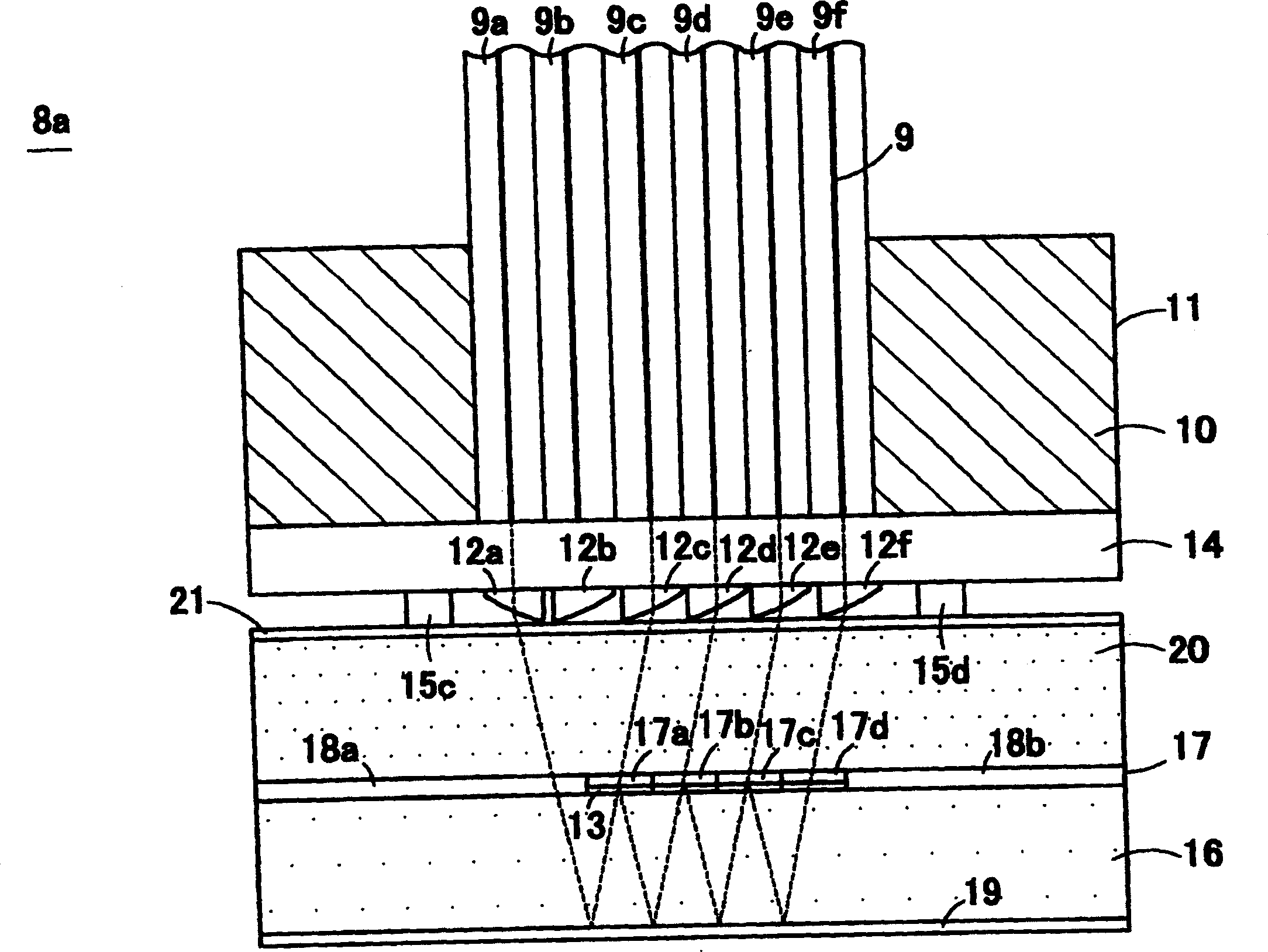
[0134] figure 2 It is a schematic exploded perspective view showing the structure of the optical multiplexer / demultiplexer 8a according to Embodiment 1 of the present invention. image 3 is through figure 2 The shown schematic cross-sectional view in the plane of the core 9 of the optical fibers 9a-9f of the optical multiplexer / demultiplexer 8a illustrates the state of wave-multiplexing or multiplexing. in addition, Figure 4 yes means figure 2 A schematic side view of the optical combiner / demultiplexer 8a shown. First, explain Figure 2-Figure 4 The structure of the optical combiner / demultiplexer 8a of the present invention is shown.

[0135] Optical multiplexer 8a of the present invention is made of transparent cover member 20 such as optical fiber array 11, microlens array 14, glass plate, spacer 15a, 15b, 15c, 15d, filter layer 17, light guide block 16, plane mirror layer 19 constitute. Here, in the optical fiber array 11, the optical fibers 9a, 9b, 9c, 9d, 9e, a...

Embodiment 2

[0176] Fig. 17 is a partial schematic sectional view of the optical multiplexer / demultiplexer 8b according to Embodiment 2 of the present invention, which is equivalent to that described in Embodiment 1. Figure 14 diagram. The optical filters 17a, 17b, 17c, 17d, and 17e are dielectric multilayer films that transmit light of wavelengths λ1, λ2, λ3, λ4, and λ5, respectively. The optical filter layer 17 is composed of a region composed of optical filters 17a-17e and a release film 13, and dummy films (spacers) 18a, 18b. The filter layer 17 can be manufactured by the manufacturing steps described in Embodiment 1. In the optical multiplexer / demultiplexer 8b shown in FIG. 17 , the description of the same configuration as that described in the first embodiment is omitted.

[0177] The optical combiner / demultiplexer 8b of this embodiment covers the surface of the filter layer 17 with a transparent, very thin film 20a such as glass to protect the filters 17a-17e from moisture. An A...

Embodiment 3

[0182] Fig. 19 is a partial schematic cross-sectional view of an optical multiplexer / demultiplexer 8c according to Embodiment 3 of the present invention, which is equivalent to that described in Embodiment 1. Figure 14 diagram. In the optical multiplexer / demultiplexer 8c shown in FIG. 19, the description of the same configuration as that described in Embodiment 1 is omitted. The filter layer 17 is composed of filters 17a-17e, a release film 13, and a dummy film 18a. The filter layer 17 can be produced by the production method described in Example 1. The optical filters 17a, 17b, 17c, 17d, and 17e are dielectric multilayer films that transmit light of wavelengths λ1, λ2, λ3, λ4, and λ5, respectively. In order to adjust the height of the microlens array 14 , spacers 31 a and 31 b are interposed between the light guide block 16 and the microlens array 14 .

[0183] In the optical multiplexer / demultiplexer 8c of this embodiment, a transparent adhesive is applied to a transpare...


PUM


Abstract

In the field of optical communication, the present invention is an optical multiplexer / demultiplexer capable of demultiplexing multiplexed optical signals of multiple wavelength regions into each wavelength region, or combining the light of each wavelength region. That is, the optical multiplexed light of wavelength λ1, λ2, λ3, λ4 is emitted from the optical fiber (9a), and its optical axis is bent by the microlens (12a) of the microlens array (14) to become parallel light, by Reflected by the plane mirror layer (19), it is incident to the filter layer (17). The filter (17a) only transmits light of wavelength λ1, so light of other wavelengths is reflected, reflected by the plane mirror layer (19) again, and enters the filter layer (17). The light transmitted through the filter (17a) is bent by the microlens (12c) to combine with the optical fiber (9c). Lights of wavelengths λ1, λ2, λ3, and λ4 are taken out from the light output ends of the optical fibers (9c, 9d, 9e, 9f), respectively.

Description

technical field [0001] The invention relates to a multi-channel, small-sized optical multiplexer and a manufacturing method of the optical multiplexer. Background technique [0002] In recent years, optical communication using optical fiber as a signal transmission medium has spread to the extent that it can be used in various households. A communication network using a wavelength multiplexing transmission method in which optical signals with different wavelengths are multiplexed and transmitted using a single optical fiber is constantly evolving. Along with this, it is desired to multiplex a plurality of lights with different wavelengths, or to downsize an optical multiplexer / demultiplexer for demultiplexing the wavelength-multiplexed light for each wavelength, and to mass-produce it at low cost. [0003] figure 1 It is a schematic side view showing the structure of an optical demultiplexer 1 of a conventional example (refer to Japanese Unexamined Patent Publication No. S...

Claims


Application Information

Patent Timeline
Patent Type & Authority Applications(China)
IPC IPC(8): G02B6/293
Inventor 古泽光一福田一喜仲西阳一大西正泰田中宏和大西彻也山本龙山濑伸基
Owner ORMON CORP
Why Eureka
Try Eureka