
Element feeding device and mounting machine therewith

A technology for component supply and electronic component installation, applied in the direction of electrical components, electrical components, etc., can solve the problems of inability to stably supply electronic components to the main body of the installation machine, inability to maintain the shuttle for electronic components, and inability to adsorb the bottom side well. Effect of stable supply of electronic components

Active Publication Date: 2005-12-07
YAMAHA MOTOR CO LTD
View PDF1 Cites 21 Cited by
  • Summary
  • Abstract
  • Description
  • Claims
  • Application Information

AI Technical Summary

Problems solved by technology

[0005] However, in the above-mentioned existing component supply device, the electronic components placed on the reciprocator are held by sucking its bottom surface, so for example, for special-shaped electronic components, sometimes the side of the bottom surface cannot be well adsorbed, and the electronic components cannot be released. Components are reliably held on the shuttle, and there is a possibility that electronic components cannot be stably supplied to the main body of the mounting machine

Method used


Image

  • Element feeding device and mounting machine therewith
  • Element feeding device and mounting machine therewith
  • Element feeding device and mounting machine therewith

Examples


Embodiment Construction

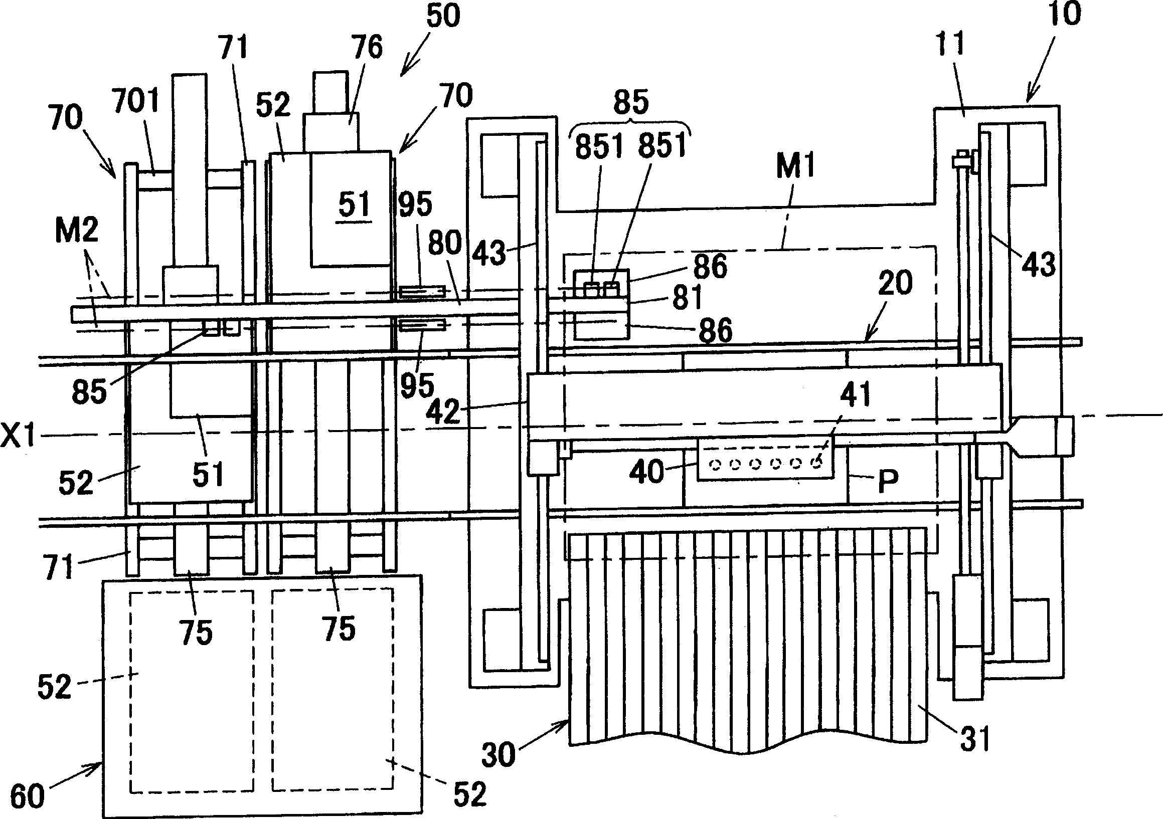
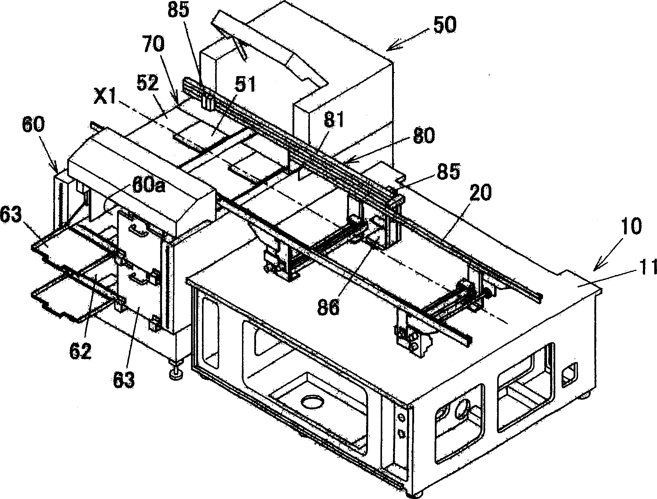
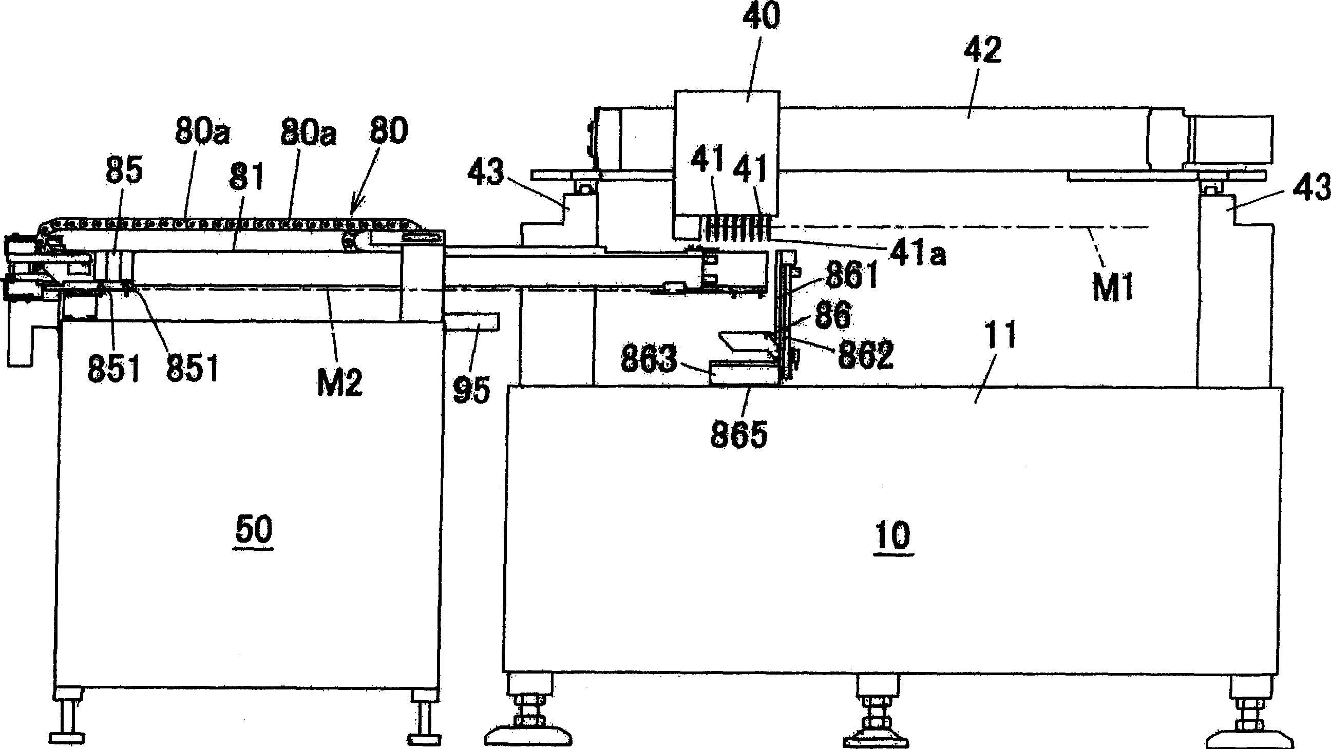
[0035] figure 1 It is a plan view of the embodiment of the mounting machine of the present invention. figure 2 is a perspective view schematically showing the mounting machine. image 3 is also a front sectional view briefly showing the mounting machine. As shown in these figures, the mounter has a mounter main body 10 and a component supply device 50 arranged side by side along a conveyance line X1 of a printed wiring board P to be mounted.

[0036] The mounting machine main body 10 is arranged along the conveying line X1 on the base 11, and has a conveyor belt 20 for conveying the printed circuit board P, a component supply unit 30 arranged on one (front side) of both sides of the conveyor belt 20, and a device. The head unit 40 for installation above the base 11 .

[0037] The component supply section 30 has a multi-row tape feeder 31 . . . suitable for supplying relatively small chip components.

[0038] Each tape feeder 31... is detachably installed with a reel, and ...


PUM


Abstract

The present invention provided a component supplying apparatus that can reliably pick up electronic components and can stably supply them to a mounting machine body. The component supplying apparatus supplies the electronic components to the mounting machine body 10 for mounting the electronic components on a substrate. The component supplying apparatus comprises an accommodation section 60 for accommodating a component tray 51 for accommodating the electronic components; a component leading mechanism 70 for leading the component tray 51 from the accommodation section 60 to a pickup region; and a component transfer mechanism 80 for transferring the electronic components in a component tray at the pickup region to a component supply position for passing the electronic components to the mounting machine body 10. The component transfer mechanism 80 comprises a transfer head 851 for picking up the electronic components from the component tray 51 at the pickup region; and a transfer head travel mechanism for moving the transfer head 851 that has picked up the electronic components to a component supply position.

Description

technical field [0001] The present invention relates to a component supply device such as a tray feeder which supplies electronic components to a mounting machine body for mounting electronic components on a circuit board to be mounted, and a mounting machine provided with the component supply device. Background technique [0002] Conventionally, as a device for supplying components to a mounting machine that mounts electronic components on a printed wiring board, there is generally known a component supply device in which component trays holding electronic components can be arranged in multiple layers up and down. [0003] For example, the component supply device disclosed in Japanese Patent Application Laid-Open No. 3-133802 is provided with a transfer reciprocating portion (guide rail) connected to the main body of the mounting machine, and a freely traveling component carrier (reciprocator) is provided on the guide rail. Then, the component supply...

Claims


Application Information

Patent Timeline
IPC IPC(8): H05K13/02
Inventor 内海智仁
Owner YAMAHA MOTOR CO LTD
Learn More