
Hybrid drive device and automobile with device mounted thereon

A technology of driving device and transmission device, which is applied in the direction of transmission device, power device, electric power device, etc. It can solve the problems of damaging the vehicle body mountability and increasing the overall length of the compound drive device, and achieves improved mountability, easy connection, and shortened length Effect

Inactive Publication Date: 2005-11-23
TOYOTA JIDOSHA KK
View PDF2 Cites 4 Cited by
  • Summary
  • Abstract
  • Description
  • Claims
  • Application Information

AI Technical Summary

Problems solved by technology

In addition, in order to suppress the size in the radial direction and ensure high torque at the time of starting, it is necessary to increase the length of the electric motor for driving in the front-rear direction accordingly, which increases the overall length of the hybrid drive device and impairs the mountability on the vehicle body.

Method used


Image

  • Hybrid drive device and automobile with device mounted thereon
  • Hybrid drive device and automobile with device mounted thereon
  • Hybrid drive device and automobile with device mounted thereon

Examples


no. 1 Embodiment approach

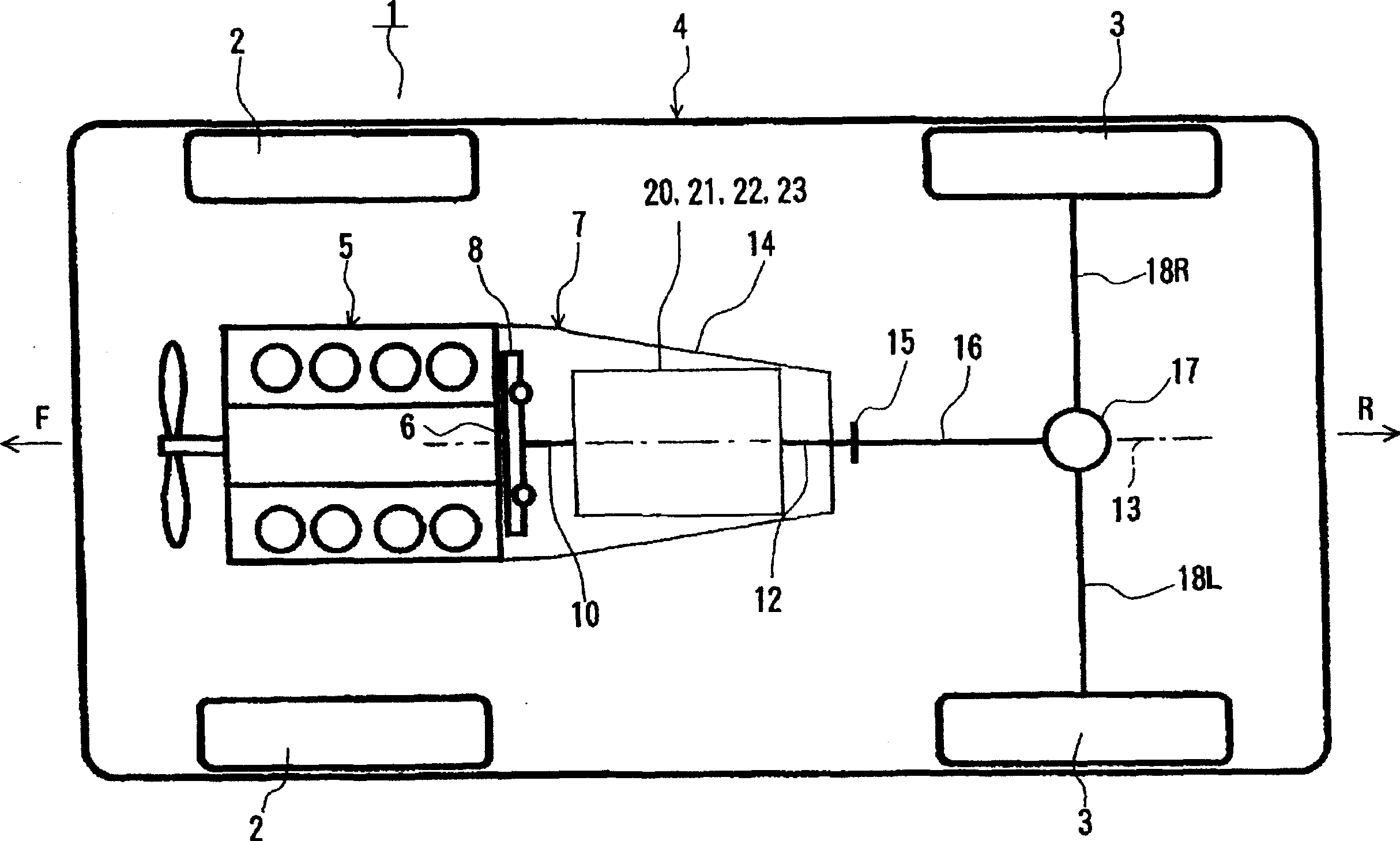
[0054] figure 1 An example of an automobile according to the present invention, that is, an automobile 1 equipped with a hybrid drive device according to the present invention is shown. The car 1 shown in the same figure is a FR (front engine, rear wheel drive) type car, and the same figure is a plan view showing its approximate structure. In addition, in an actual automobile, the arrow F direction in the figure is the front side, and the arrow R direction is the rear side.

[0055] The automobile 1 shown in the figure has a vehicle body 4 supported by left and right front wheels 2, 2 and left and right rear wheels 3, 3 as driving wheels. The internal combustion engine 5 is mounted in the front portion of the vehicle body 4 via a rubber mount (not shown), and a crankshaft 6 as an output shaft thereof faces in the front-rear direction. In addition, in the same figure, the output shaft formed by the rear protrusion part of a crankshaft is the crankshaft 6 shown in figure. The...

no. 2 Embodiment approach

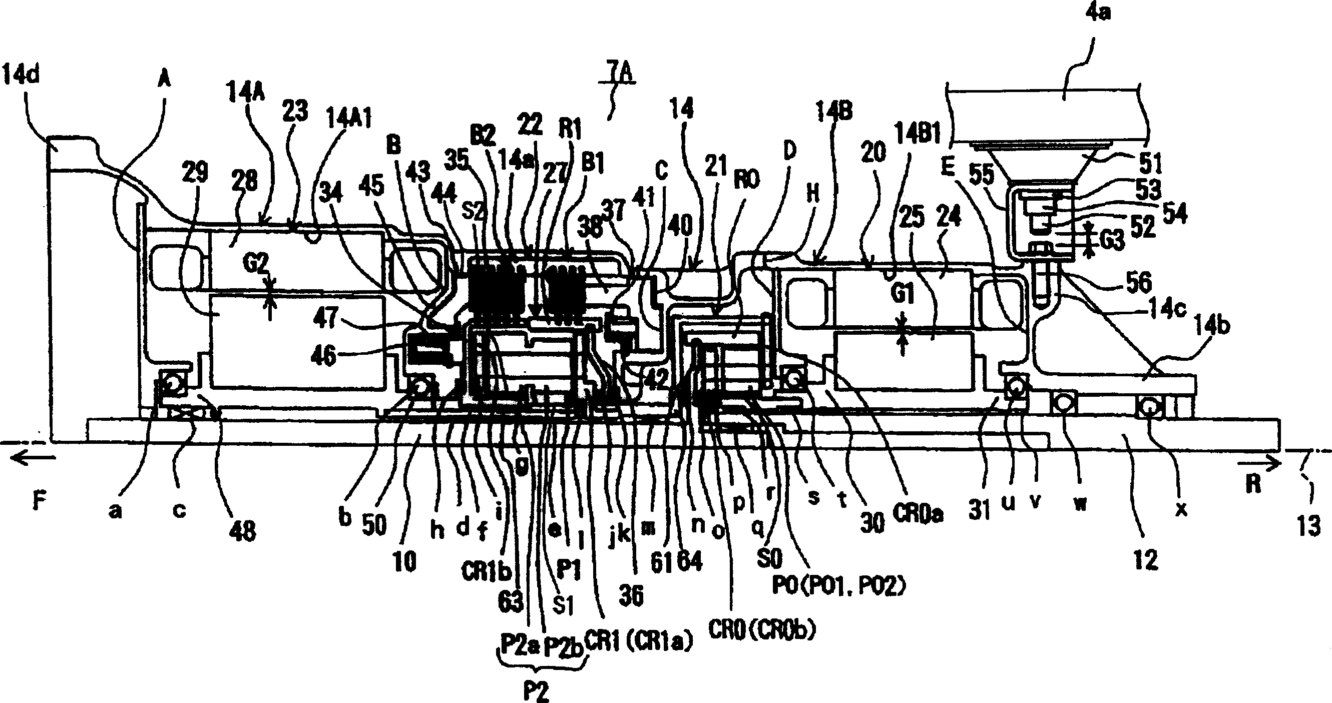
[0097] Next, as a piggyback on figure 1 As another example of the hybrid drive device 7 according to the present invention in the automobile 1 shown, the hybrid drive device 7B according to the present embodiment will be described. First, refer to Figure 4 The skeleton diagram of , illustrating the general situation of the compound drive device 7B as a whole, and then refer to Figure 5 , describe the specific structure in detail. In these figures, the arrow F direction is the front side of the vehicle body (internal combustion engine side), and the arrow R direction is the vehicle body rear side (differential gear side).

[0098] like Figure 4 As shown, the compound drive unit 7B moves from close to figure 1 From the internal combustion engine 5 side, that is, from the front side to the rear side, the second electric motor 23, the speed change device 22, the first electric motor 20, and the planetary gear 21 for power distribution are sequentially arranged. These are a...


PUM


Abstract

A hybrid driving unit (7) in which a second electric motor (23) is disposed on the side closer to the front (the side closer to an internal combustion engine (5)) than a first electric motor (20). A casing member (14) is formed such that an inner diameter of a part thereof in which a stator (28) of the second electric motor (23) is fixed is larger than that of a part in which a stator of the first electric motor (20) is fixed. It allows the second electric motor (23) to be constructed so as to have a large radial dimension and to that extent, allows the length thereof in the longitudinal direction to be suppressed. Accordingly, it allows the length of the whole hybrid driving unit (7) to be shortened.

Description

technical field [0001] The present invention relates to a compound drive device mounted on an automobile and an automobile equipped with the device, and particularly relates to the arrangement of two electric motors, a planetary gear for power distribution, and a speed change device in a case member. Background technique [0002] In a well-known hybrid drive system mounted on a car in the past, the engine, generator, and drive (auxiliary) electric motor are respectively connected to the three elements of the planetary gear, and the drive electric motor is connected to the output shaft. Control the generator to control the output torque of the planetary gear steplessly, and combine the torque of other driving electric motors with the output torque of the planetary gear to the output shaft as needed, which is the so-called mechanical Combined drive unit with distribution method (separate type or 2-motor type). [0003] Among the above-mentioned compound drive devices, there i...

Claims


Application Information

Patent Timeline
IPC IPC(8): B60K1/02B60K6/365B60K6/40B60K6/445B60K6/547B60L50/16F16H3/72
CPCY02T10/6239F16H3/728B60K1/02Y10S903/911B60K6/365B60K6/547F16H2037/0873B60K6/40B60K6/445Y02T10/62
Inventor 加纳成吾表贤司和久田聪稻垣知亲足立昌俊小嵨昌洋
Owner TOYOTA JIDOSHA KK
Learn More