
Thread tube of open end spinning arrangement

A technology of air spinning and yarn guide, applied in the field of yarn guide, can solve problems such as poor strength and uniformity, achieve good yarn value, improve yarn quality, and improve spinning stability.

Inactive Publication Date: 2005-11-02
MASCHINENFABRIK RIETER AG
View PDF4 Cites 8 Cited by
  • Summary
  • Abstract
  • Description
  • Claims
  • Application Information

AI Technical Summary

Problems solved by technology

In the end they are very coarse textile elements, as strength and uniformity are extremely poor due to damage to the finished yarn by breaking individual fibers to create pile

Method used


Image

  • Thread tube of open end spinning arrangement
  • Thread tube of open end spinning arrangement
  • Thread tube of open end spinning arrangement

Examples


Embodiment Construction

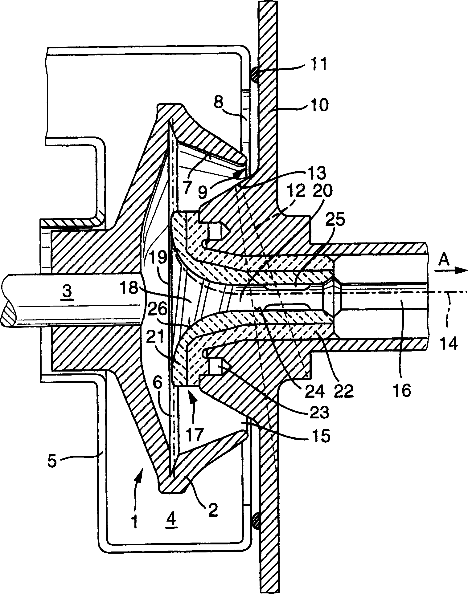
[0022] figure 1 The open-end rotor spinning device, shown only partially in , comprises a rotor 1 consisting of a cup disc 2 and a mandrel 3 pressed into it. The arbor 3 is supported and driven in a manner not shown. The cup and plate 2 rotate in the negative pressure chamber 4 formed by the cup shell 5 when working, and the cup shell is connected on the negative pressure source in a manner not shown.

[0023] The cup tray 2 has a fiber sliding surface 7 that expands conically toward the fiber collecting groove 6 . In the fiber collection groove 6, the diameter of the hollow cavity of the cup and tray 2 is the largest. The rotor 1 can be pulled out through the front opening 8 of the cup housing 5 towards the operating surface of the open-end rotor spinning device. In operation, this opening 8 of the cup shell 5 together with the open front 9 of the cup tray 2 is closed by a removable guard 10 . The guard plate 10 is tightly attached to the cup shell 5 by connecting an annu...


PUM


Abstract

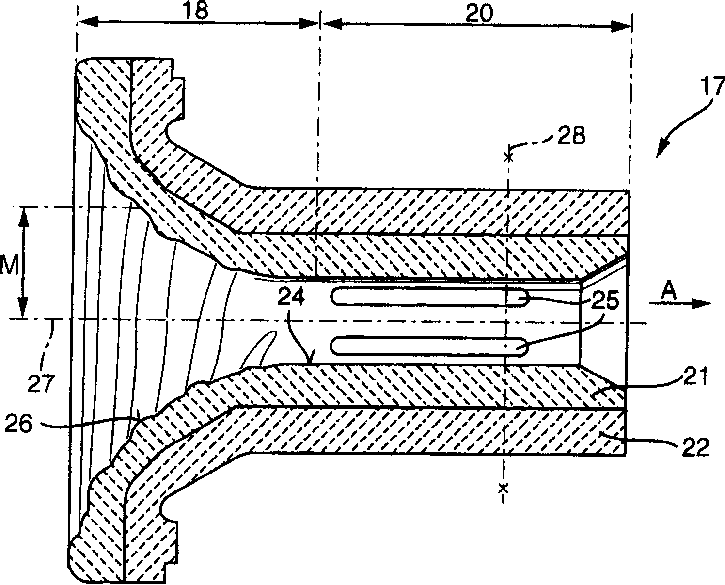
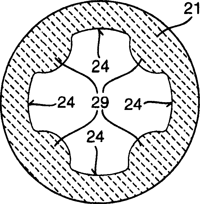
The invention relates to a yarn guide tube for an open-end air spinning device. In the yarn deflection area, the yarn guide tube has a helical structure, which extends essentially continuously over the entire yarn deflection area without interruption. In addition, a further formation consisting of gentle elevations or gentle depressions follows the inner helical formation of the tube throat of the yarn guide tube. Both structures are constructed so that they can transmit forces to the yarn without damaging the yarn.

Description

technical field [0001] The invention relates to a yarn guide tube for an open-end open-end spinning device, with a yarn deflection zone and a tube throat, wherein, there are means for increasing the spinning stability, and in the yarn deflection The region also has a helical structure. Background technique [0002] Spinning stability problems often arise on open-end spinning machines because the actual yarn twist introduced is not uniform at the end of the yarn. The introduction of the twist is mainly carried out between the yarn guide tube and the doffing mechanism of the finished yarn. It often deteriorates in the area between the cup groove and the guide tube. Too low a twist in this area means lower spinning stability, because below a certain twist, new fibers can no longer be incorporated perfectly into the yarn end, resulting in yarn breakage. This problem is acute, since the composition of the yarn guide tube has a decisive influence not only on the spinning stabil...

Claims


Application Information

Patent Timeline
Patent Type & Authority Applications(China)
IPC IPC(8): D01H4/00D01H4/40
CPCD01H4/40
Inventor G·鲍尔
Owner MASCHINENFABRIK RIETER AG
Learn More