Reversible back-boost chopper circuit, and inverter circuit with the same
A technology of step-up chopping and reverse polarity, applied in the direction of converting irreversible DC power input into AC power output, adjusting electric variables, instruments, etc., can solve the problem of weakening magnetic field, increasing output current, and difficulty in cooling the inverter correctly circuit problems
- Summary
- Abstract
- Description
- Claims
- Application Information
AI Technical Summary
Problems solved by technology
Method used
Image
Examples
no. 1 example
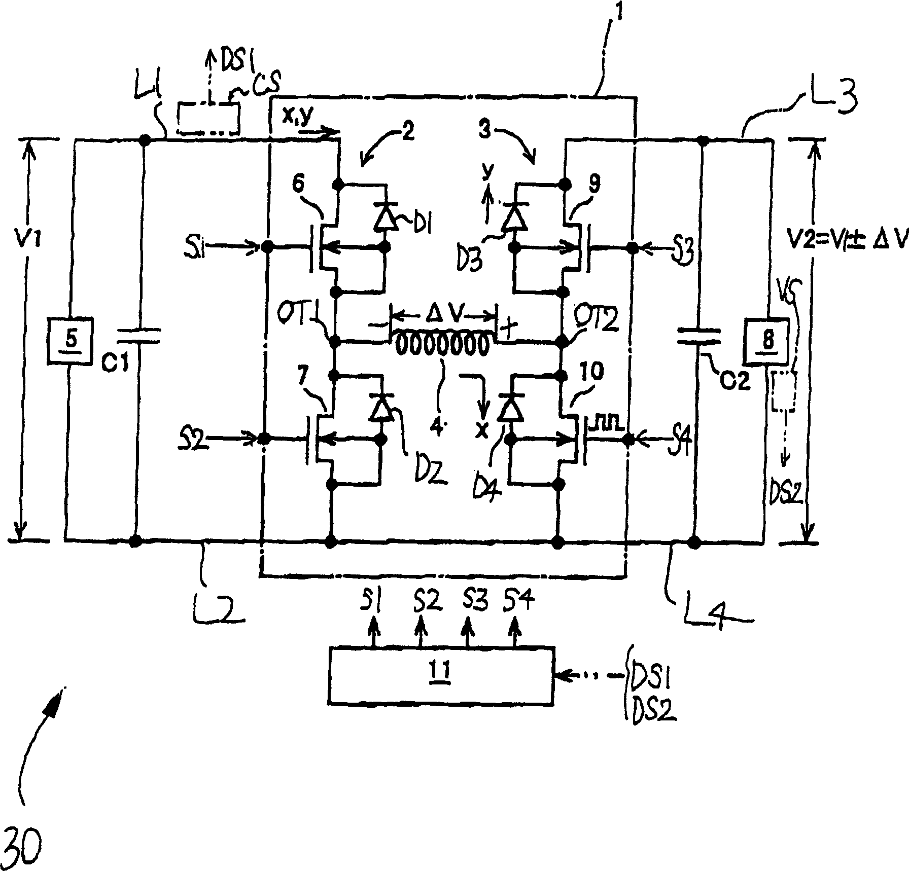
[0031] Hereinafter, an inverter circuit of a motor drive according to a first embodiment of the present invention will be described with reference to the drawings.
[0032] The structure of the inverter circuit includes the chopper circuit.
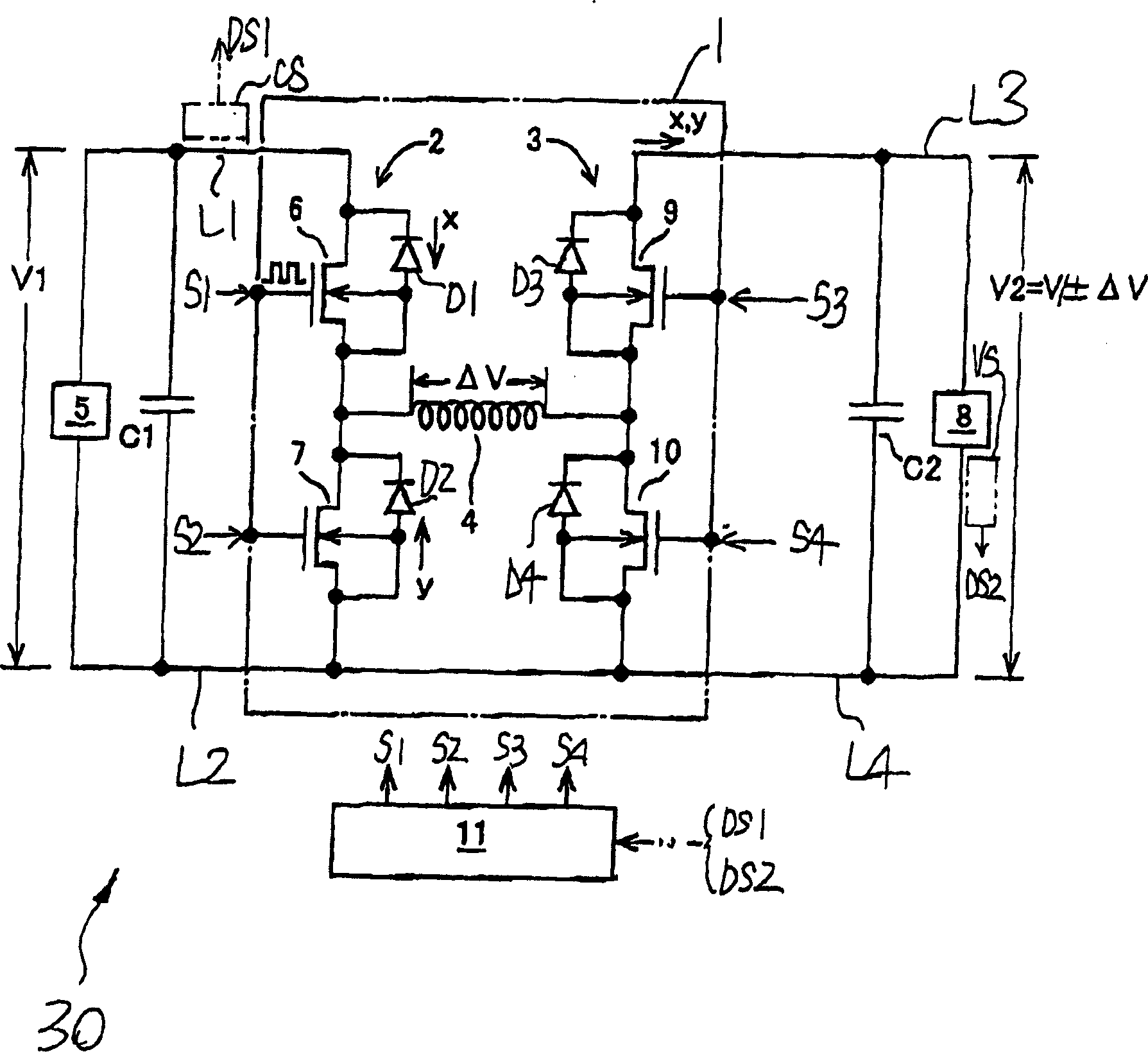
[0033] Such as Figure 1A As shown in , the inverter circuit 30 has a chopper circuit 1 and a first smoothing capacitor C1, which is an example of a first voltage smoothing circuit according to the present invention. A first smoothing capacitor C1 is located at one of the input / output terminals of the chopper circuit 1 . The inverter circuit 30 has a second smoothing capacitor C2, which is an example of a second voltage smoothing circuit according to the present invention, at the other input / output terminal of the chopper circuit 1. middle.
[0034] The chopper circuit 1 has a power-side half-bridge circuit 2, a load-side half-bridge circuit 3, and a reactor 4 such as a choke coil.
[0035] The half-bridge circuit 2 at the power supply...
no. 2 example
[0114] Attach the reference Figure 6 An inverter circuit according to a second embodiment of the present invention will be described. The inverter circuit uses a plurality of chopper circuits 1 shown in FIG. 1 and is operable to drive a three-phase motor / generator. By the way, in Figure 6 , the number of chopper circuits according to the first embodiment is set to be twice or more the number of phases (three) of the three-phase motor. For example, twelve chopper circuits 111 to 122 are provided per phase.
[0115] Only the U-phase inverter circuit 110 is exemplified in order to briefly describe the inverter circuit according to the second embodiment. The U-phase inverter circuit 110 has twelve chopper circuits 111 to 112 each having substantially the same structure as the chopper circuit 1 . The chopper circuits 111 to 122 are connected in parallel with each other.
[0116] Each on-time (or off-time) of each switching element of each chopper circuit 111 to 112 is sequen...
PUM
 Abstract
Description
Claims
Application Information
 - Generate Ideas
- Intellectual Property
- Life Sciences
- Materials
- Tech Scout
- Unparalleled Data Quality
- Higher Quality Content
- 60% Fewer Hallucinations
Browse by: Latest US Patents, China's latest patents, Technical Efficacy Thesaurus, Application Domain, Technology Topic, Popular Technical Reports.
© 2025 PatSnap. All rights reserved.Legal|Privacy policy|Modern Slavery Act Transparency Statement|Sitemap|About US| Contact US: help@patsnap.com


