
String inverter and boost chopper circuit control method thereof

A boost chopper, circuit control technology, applied in control/regulation systems, irreversible DC power input conversion to AC power output, instruments, etc., can solve the problem of increased switching loss, increased wafer temperature, incompatibility and other problems, to achieve the effect of reducing switching loss and reducing current ripple

Active Publication Date: 2019-05-28
SUNGROW POWER SUPPLY CO LTD
View PDF15 Cites 9 Cited by
  • Summary
  • Abstract
  • Description
  • Claims
  • Application Information

AI Technical Summary

Problems solved by technology

However, when the input and output voltages of the Boost circuit remain unchanged, in order to reduce the current ripple of its reactance, it is necessary to increase the switching frequency; however, the higher the switching frequency, the more switching times per unit time, and the corresponding switching loss becomes Larger, the wafer temperature rises, and the efficiency becomes smaller; therefore, the existing technology cannot be compatible with the two constraints of current ripple and switching loss

Method used


Image

  • String inverter and boost chopper circuit control method thereof
  • String inverter and boost chopper circuit control method thereof
  • String inverter and boost chopper circuit control method thereof

Examples


Embodiment Construction

[0034] The following will clearly and completely describe the technical solutions in the embodiments of the application with reference to the drawings in the embodiments of the application. Apparently, the described embodiments are only some of the embodiments of the application, not all of them. Based on the embodiments in this application, all other embodiments obtained by persons of ordinary skill in the art without creative efforts fall within the protection scope of this application.

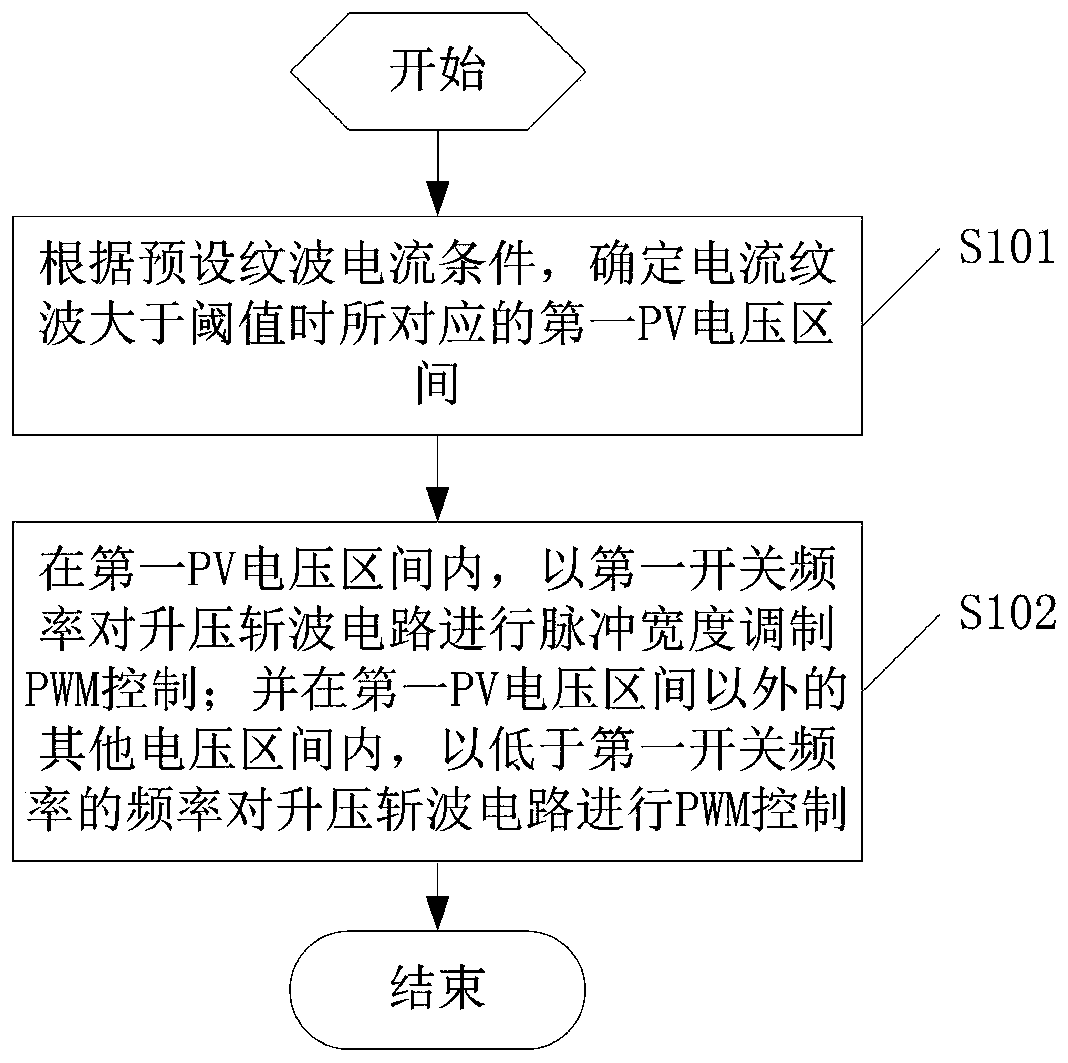
[0035] The present invention provides a method for controlling a step-up chopper circuit of a string inverter, in order to provide a control scheme for a step-up chopper circuit that can be compatible with the two restrictive conditions of current ripple and switching loss.

[0036] The structure of the string inverter is as follows figure 1 As shown, including: controller (not shown in the figure), bus capacitor branch (C1 and C2), inverter circuit, filter circuit and at least one step-up ...


PUM


Abstract

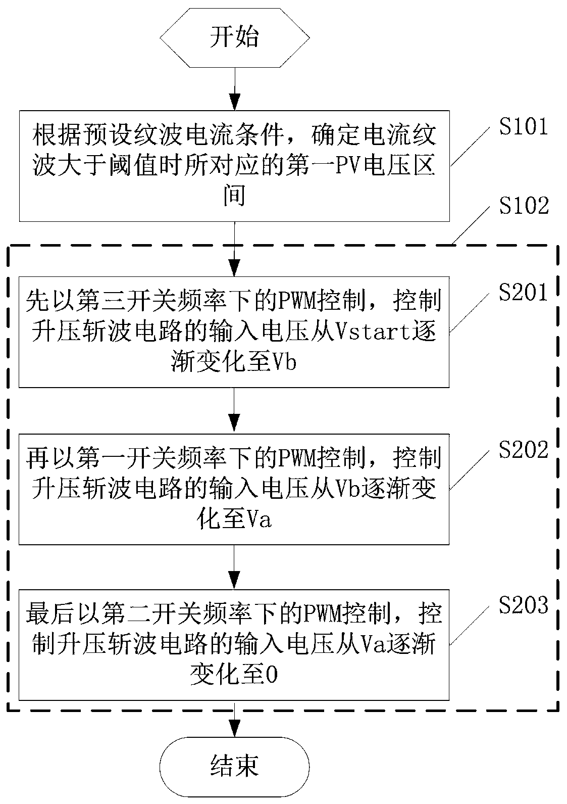
The invention provides a string inverter and a boost chopper circuit control method thereof, and the method comprises the steps: firstly, determining a corresponding first PV voltage interval when a current ripple is greater than a threshold value according to a preset ripple current condition; performing PWM control on the boost chopper circuit at a first switching frequency in the first PV voltage interval; and performing PWM control on the boost chopper circuit at a frequency lower than the first switching frequency in other voltage intervals except the first PV voltage interval. Namely, when PWM control is carried out on the boost chopper circuit, control is carried out in a PV voltage interval with relatively high current ripples by adopting relatively high switching frequency, so that the current ripples are reduced. In a PV voltage interval with relatively small current ripple, relatively low switching frequency is adopted for control, so that the switching loss is reduced, therefore, two restriction conditions of current ripples and switching loss can be compatible.

Description

technical field [0001] The invention relates to the technical field of power electronics, in particular to a string inverter and a control method for a step-up chopper circuit thereof. Background technique [0002] Due to the characteristics of the photovoltaic cell itself, its maximum power point is between an open circuit and a short circuit; and as the environment such as light changes, its maximum power point will also change constantly; so it is usually necessary to adjust the inverter control. Maximum power point tracking to make it work at the maximum power point. [0003] However, in practical applications, due to the characteristics of the inverter circuit, the bus voltage must be greater than the minimum grid-connected voltage, so the bus voltage cannot be reduced without limit. wave circuit; such as figure 1 The input terminals of each Boost circuit in the shown string inverter are connected to the corresponding PV components, and the output terminals are connec...

Claims


Application Information

Patent Timeline
IPC IPC(8): H02M3/156H02M7/48H02M1/14
CPCY02E10/56
Inventor 张涛邢军
Owner SUNGROW POWER SUPPLY CO LTD
Learn More