Micro fluid jet unit and method of improving micro fluid jetting quality
A spraying device and microfluidic technology, applied in printing devices, printing, etc., can solve problems such as printing quality degradation
- Summary
- Abstract
- Description
- Claims
- Application Information
AI Technical Summary
Problems solved by technology
Method used
Image

Examples
no. 1 example
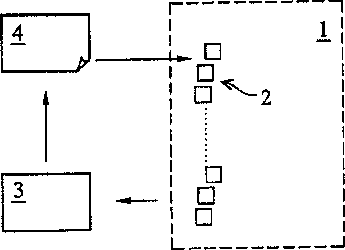
[0036] Figure 4 is a schematic block diagram showing the first embodiment of the present invention. According to the aforementioned test results, before fluid injection, a preferred embodiment of the present invention is to first measure the distribution range of the resistance value of each heater in the microfluid injection device, and if it meets the preset specification range, start Originally set standard driving conditions. If not, adjusting driving conditions for all heaters of the microfluid ejection device to improve ejection quality. see Figure 4 After measuring the distribution range of the resistance value of each heater in the microfluid ejection device, the heater 5 with abnormal resistance value and the heater 6 with normal resistance value are obtained. The driving condition 7 is adjusted for all the heaters of the micro-fluid ejection device, and the ejection action is performed to improve the ejection quality of the micro-fluid ejection device.
no. 2 example
[0038] Figure 5 is a schematic block diagram showing a second embodiment of the present invention. In this embodiment, if the driving conditions are adjusted for all the heaters of the microfluid ejection device to improve the ejection quality according to the aforementioned test results. Although the preferred injection efficiency can be maintained, in the case of prolonging the heating time, abnormal injection conditions will occur in the heaters that originally sprayed normally. Therefore, before fluid injection, another preferred embodiment of the present invention is to first measure the resistance value of each heater in the microfluid injection device, and only adjust the driving conditions for heaters that exceed the standard, so as to improve the injection quality. see Figure 4 After measuring the distribution range of the resistance value of each heater in the microfluid ejection device, the heater 5 with abnormal resistance value and the heater 6 with normal res...
PUM
 Abstract
Description
Claims
Application Information
 - R&D
- Intellectual Property
- Life Sciences
- Materials
- Tech Scout
- Unparalleled Data Quality
- Higher Quality Content
- 60% Fewer Hallucinations
Browse by: Latest US Patents, China's latest patents, Technical Efficacy Thesaurus, Application Domain, Technology Topic, Popular Technical Reports.
© 2025 PatSnap. All rights reserved.Legal|Privacy policy|Modern Slavery Act Transparency Statement|Sitemap|About US| Contact US: help@patsnap.com