
Respiration tube disinfecting machine

The technology of breathing tube and disinfection machine is applied in the innovative technology field of breathing tube disinfection machine, which can solve the problems of long drying time, secondary pollution of breathing tube and accessories, and the inability of patients to meet the needs, and achieves simple structure, low price, good performance effect

Active Publication Date: 2005-09-14
GUANGDONG VANWARD NEW ELECTRIC CO LTD
View PDF0 Cites 4 Cited by
  • Summary
  • Abstract
  • Description
  • Claims
  • Application Information

AI Technical Summary

Problems solved by technology

[0002] At present, medical breathing tubes and accessories are mainly used for oxygen supply and ventilation of critically ill patients. When used, they will directly infect the bacteria and viruses in the patient's respiratory tract. Due to the high price of breathing tubes and accessories, they cannot be made into disposable medical supplies, so it is necessary Disinfect and recycle after use
The disinfection method currently used is to clean first, then soak and disinfect with disinfectant water, and then take it out to dry. There are two main problems in operation: one is that there is no special equipment when drying, and there is no special storage device after drying, which is easy to cause Secondary pollution of breathing tubes and accessories. Second, it takes a long time from cleaning to drying, and the inventory of breathing tubes and accessories is limited, which cannot meet the demand when there are many patients.
[0003] According to the survey, the vast majority of medical institutions are not equipped with special breathing tube disinfection machines. The main reason is that the current breathing tube disinfection machines are completely imported and the price is quite expensive. However, after the SARS storm, all medical institutions dare not Neglect, more attention is paid to the disinfection of breathing tubes, and there is an urgent need to replace imported products with cheap and high-quality breathing tube disinfection machines

Method used

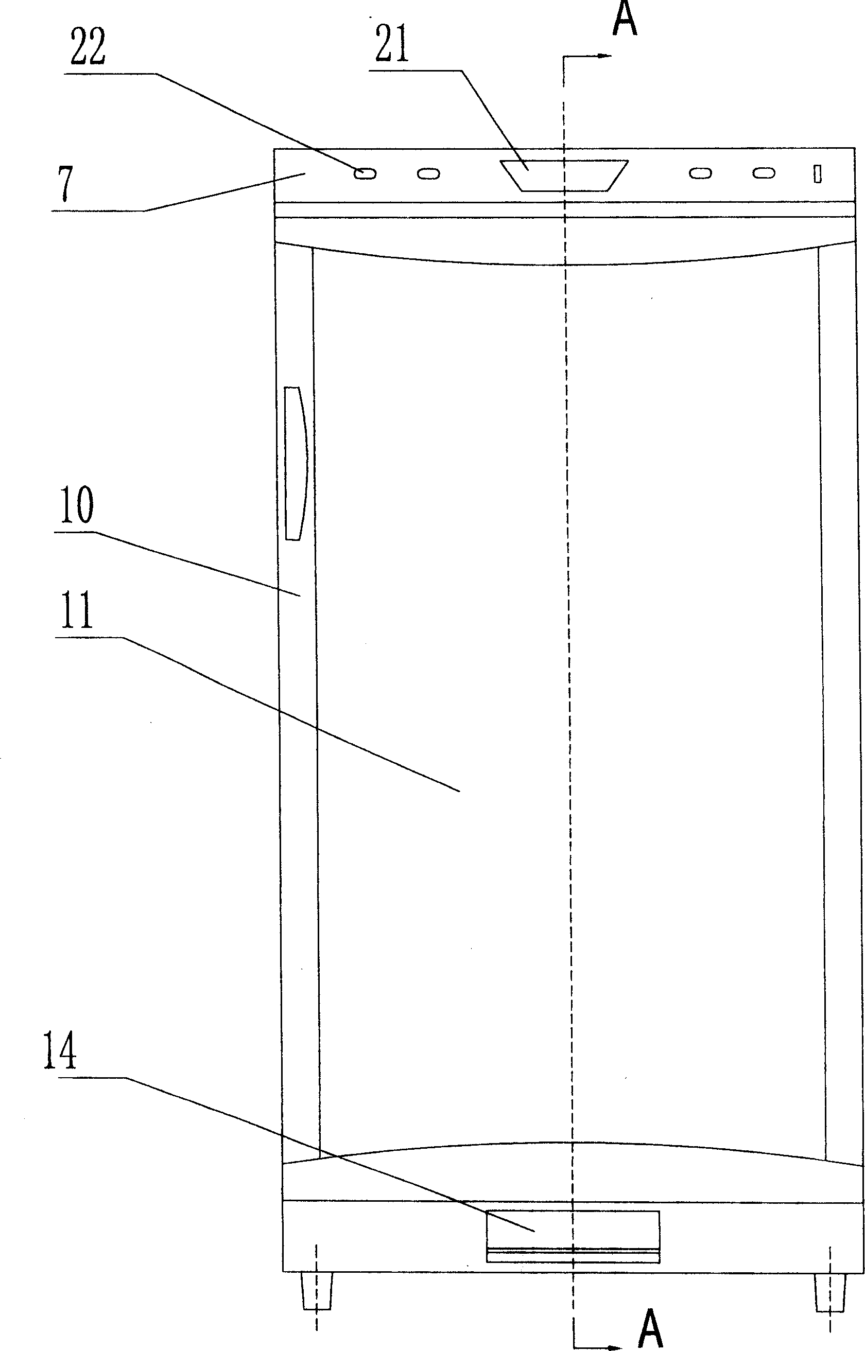
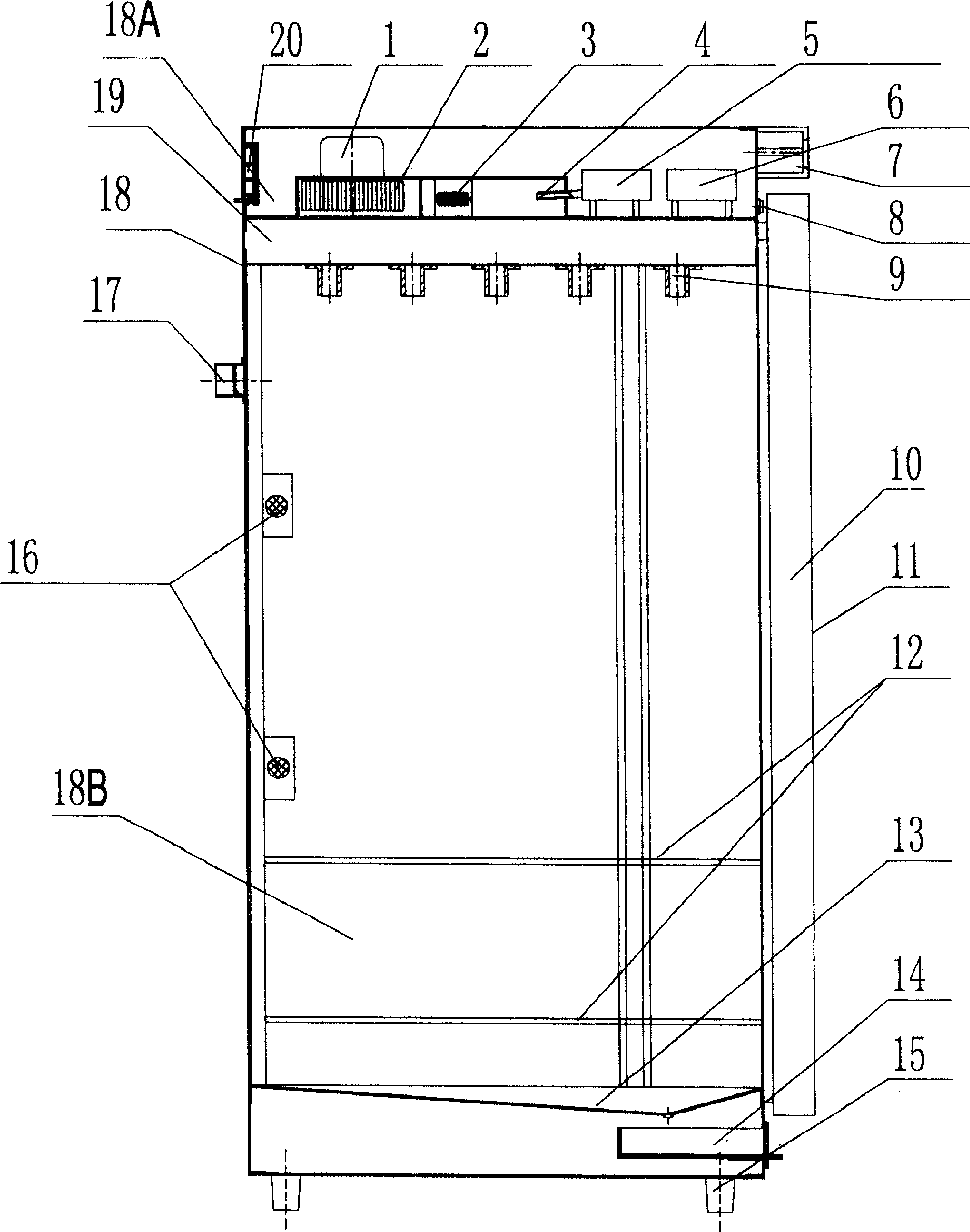
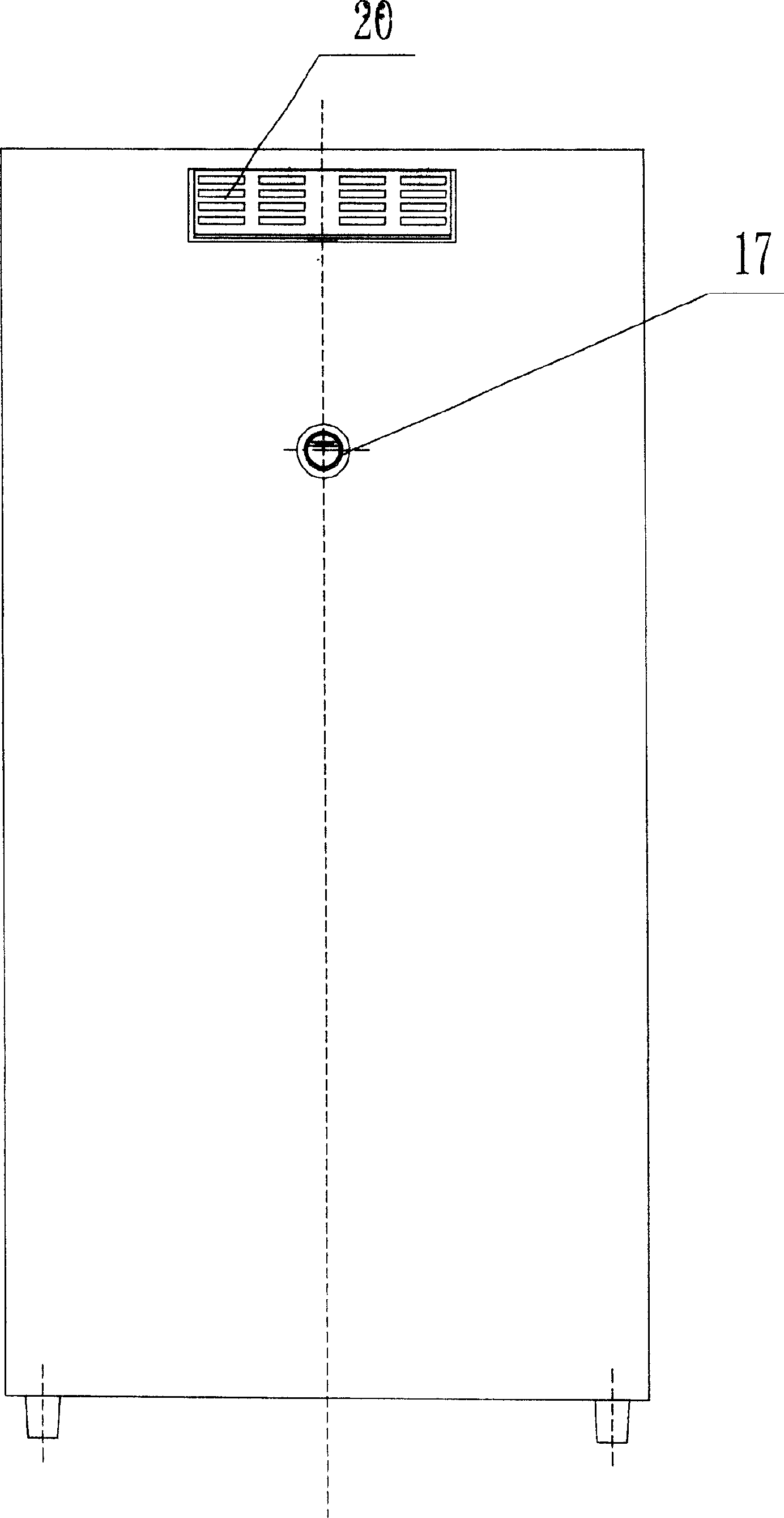

Image

  • Respiration tube disinfecting machine
  • Respiration tube disinfecting machine
  • Respiration tube disinfecting machine

Examples


Embodiment

[0020] The structure diagram of the present invention is as figure 1 , 2 , 3, including a hot air device, an ozone generator (5), a casing (18), a door body (10) and a control device thereof, wherein the casing (18) is provided with a cavity body which is divided into upper The supporting plate (19) of chamber (18A) and lower chamber (18B), hot air device includes motor (1), wind wheel (2), heater (3), motor (1), wind wheel (2), heating Device (3), ozone generating device (5) are all installed on the top surface of support plate (19), and the wind wheel (2) driven by motor (1) is placed on the side of heater (3), ozone generation The air inlet (4) of the device (5) is opposite to the hot air device, and the bottom of the support plate (19) is provided with a port (9) that communicates with the upper chamber (18A) and can be nested with a breathing tube. The motor (1), heating The device (3) and the ozone generator (5) are electrically connected with the control device. Thro...


PUM


Abstract

The invention relates to siphon tube disinfector for disinfecting medical siphon tube and attachment. It comprises a hot air apparatus, an ozonizer (5), a box (18), a gate (10), and its control device. And a facing bar (19) separates the cavity of box (18) into upper cavity (18A) and lower cavity (18B); the hot air apparatus comprises generator (10), windwheel (2), calorifier (3) while the generator (10), windwheel (2), calorifier (3) and ozonizer (5) are mounted on the top surface of facing bar (19). The windwheel (2) droved by generator (1) are mounted on the side of calorifier. A port mounted on the bottom of facing bar is through the upper cavity (18A) and can be inserted siphon tube. A ultraviolet ozonizer is installed on the inner back wall of box (18). Said invention utilizes combined structure comprising hot air apparatus, ozonizer, and ozonizer which can meet the disinfection demand of siphon tube while low in cost and price.

Description

1. Technical field: [0001] The invention relates to a breathing tube sterilizing machine for sterilizing medical breathing tubes and accessories, which belongs to the innovative technology of the breathing tube sterilizing machine. 2. Background technology: [0002] At present, medical breathing tubes and accessories are mainly used for oxygen supply and ventilation of critically ill patients. When used, they will directly infect the bacteria and viruses in the patient's respiratory tract. Due to the high price of breathing tubes and accessories, they cannot be made into disposable medical supplies, so it is necessary Disinfect and recycle after use. The disinfection method currently used is to clean first, then soak and disinfect with disinfectant water, and then take it out to dry. There are two main problems in operation: one is that there is no special equipment when drying, and there is no special storage device after drying, which is easy to cause Secondary pollution ...

Claims


Application Information

Patent Timeline
IPC IPC(8): A61L2/00A61L2/06A61L2/20
Inventor 黄上武
Owner GUANGDONG VANWARD NEW ELECTRIC CO LTD
Learn More