Balance detection and correction apparatus for magneto rotors
A rotor balancing and correcting device technology, which is applied in the direction of motor generator testing, centering/balancing rotors, etc., can solve the problems of increased processing costs, high uniformity requirements, and increased costs, achieving cost reduction, high calibration accuracy, and The effect of improving efficiency
- Summary
- Abstract
- Description
- Claims
- Application Information
AI Technical Summary
Problems solved by technology
Method used
Image


Examples
Embodiment 1
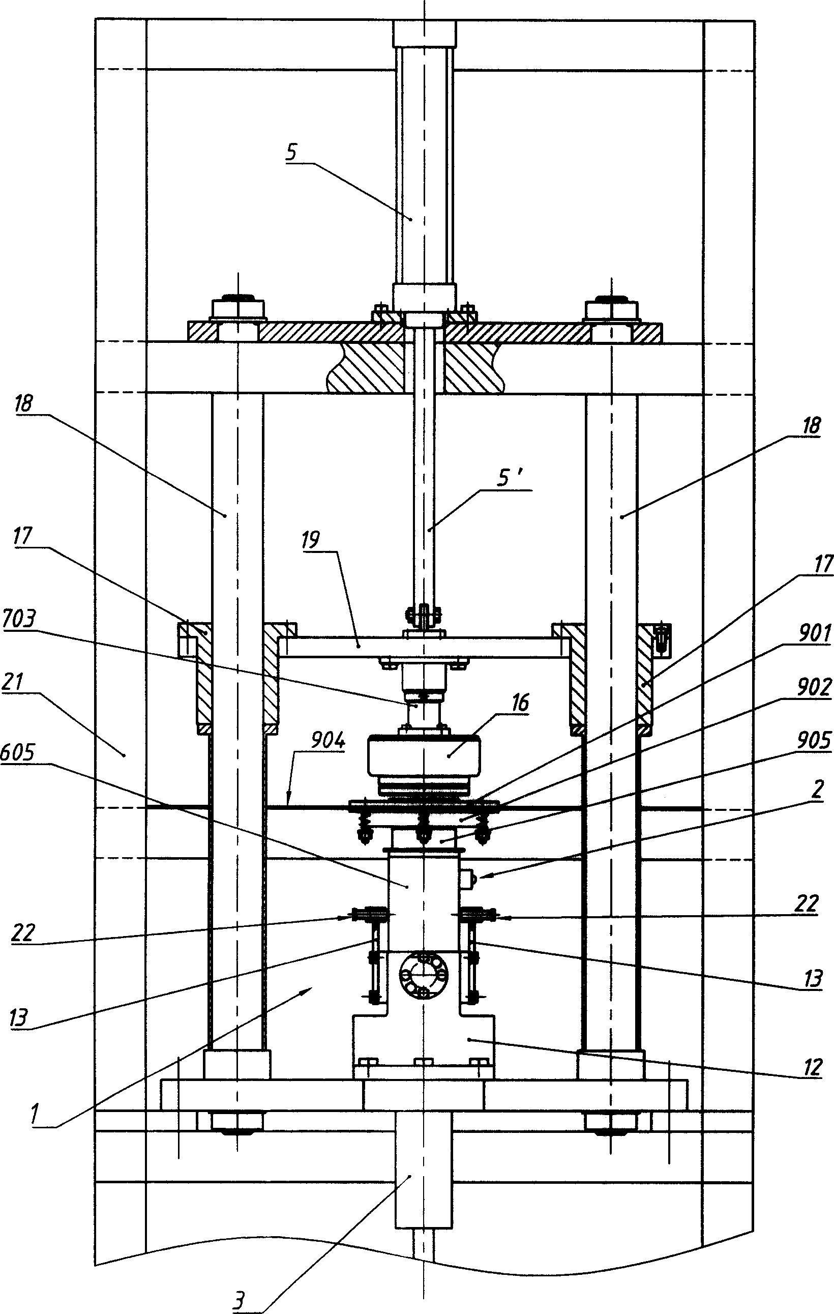
[0023] A magneto rotor balance detection and correction device. The magneto rotor 16 is set on a positioning sleeve 602 in the state that the open end (reserved for loading into the magneto stator) faces the positioning and pressing head 701, and the positioning sleeve 602 is sleeved on the central shaft 601 in a loose fit (The matching surfaces of the two have been finely ground in advance, and the matching accuracy is IT4~IT6). The rear end of the positioning sleeve 602 has a flange plate that is pressed on a mounting collar 610 positioned at the front portion of the central shaft 601. The flange plate has two to four screw holes, and the mounting collar 610 has a The threaded hole corresponding to the screw through hole has a positioning sleeve pressing plate 603 that also has a corresponding screw through hole to press the flange and fix the positioning sleeve 602 on the installation collar 610 by connecting screws 609 . The threaded holes and the screw through holes are ...
Embodiment 2
[0027] There is only one difference between this example and Embodiment 1, and the similarities will not be repeated. The different parts are: (see Figure 5) The compression sleeve 703 is pressed against the inner end surface of the positioning compression head 701 by a spring 705 . There is a flange at the inner end of the positioning compression head 701, and a thrust bearing 706 is installed on the end face of the flange, and a spring guide post 704 and a spring guide post 704 are pressed on the other end face of the thrust bearing 706. The spring 705 that is enclosed within on this spring guide post 704, the two ends of this spring 705 respectively bear against the endoporus bottom of this compression sleeve 703 and the spring seat surface of spring guide post 704 (in this example, this endoporus is due to Because of the size, it extends through the bearing connecting plate 19, and its bottom is the lower end surface of the cylinder connecting plate 20); between the part...
Embodiment 3
[0029] As can be seen from Embodiment 1 or 2, when the magneto rotor 16 is taken off from the central shaft 601, only existing methods can be used. This example is based on these two examples, the improvement of this part of the existing structure (see Figure 4 , 6 ). The parts identical to these two examples are not described in detail. The improved content is that there is a device that can eject the magneto rotor 16 around its central axis 601 on the side of the magneto rotor 16 away from the pressing device. The central axis 601 is a coaxial plunger type annular cylinder. The cylinder body 902 of this air cylinder is its mouth along the hollow mountain shape facing the magneto rotor 16, and the mouth has a flange on the outside. There is a distance of 0.5 to 2 mm between the front faces of a thrust collar 611 at the rear of 610 (it is intended to prevent it from contacting other components when the annular cylinder is not working, and to push it quickly when it is work...
PUM
 Abstract
Description
Claims
Application Information
 - R&D
- Intellectual Property
- Life Sciences
- Materials
- Tech Scout
- Unparalleled Data Quality
- Higher Quality Content
- 60% Fewer Hallucinations
Browse by: Latest US Patents, China's latest patents, Technical Efficacy Thesaurus, Application Domain, Technology Topic, Popular Technical Reports.
© 2025 PatSnap. All rights reserved.Legal|Privacy policy|Modern Slavery Act Transparency Statement|Sitemap|About US| Contact US: help@patsnap.com