
Liquid crystal display device

A technology of liquid crystal display and equipment, applied in the field of liquid crystal display equipment, can solve the problems of undisclosed driving operation, unprovided, unmentioned data side integrated circuit input and output signal power supply potential and data input signal potential relationship, etc.

Inactive Publication Date: 2005-07-27
CITIZEN WATCH CO LTD +1
View PDF4 Cites 0 Cited by
  • Summary
  • Abstract
  • Description
  • Claims
  • Application Information

AI Technical Summary

Problems solved by technology

Therefore, the requirement that the segment driver is provided separately from the drain driver does not fully meet the space saving and cost reduction needs of the portable electronic terminal.
[0007] Also, in the inventions disclosed in Japanese Patent Application Laid-Open Nos. 2001-183998 and 2001-184000, there is no mention of the specific input and output signals of the integrated circuit on the data side, or the power supply potential of the common electrode and the connection of the data input signal. The relationship between potential
Also, no suggestion is given regarding problems in DC driving caused by the relationship between the power supply potential of the common electrode and the potential of the data output signal
Also, the driver action to mitigate the issue is not disclosed

Method used


Image

  • Liquid crystal display device
  • Liquid crystal display device
  • Liquid crystal display device

Examples


Embodiment Construction

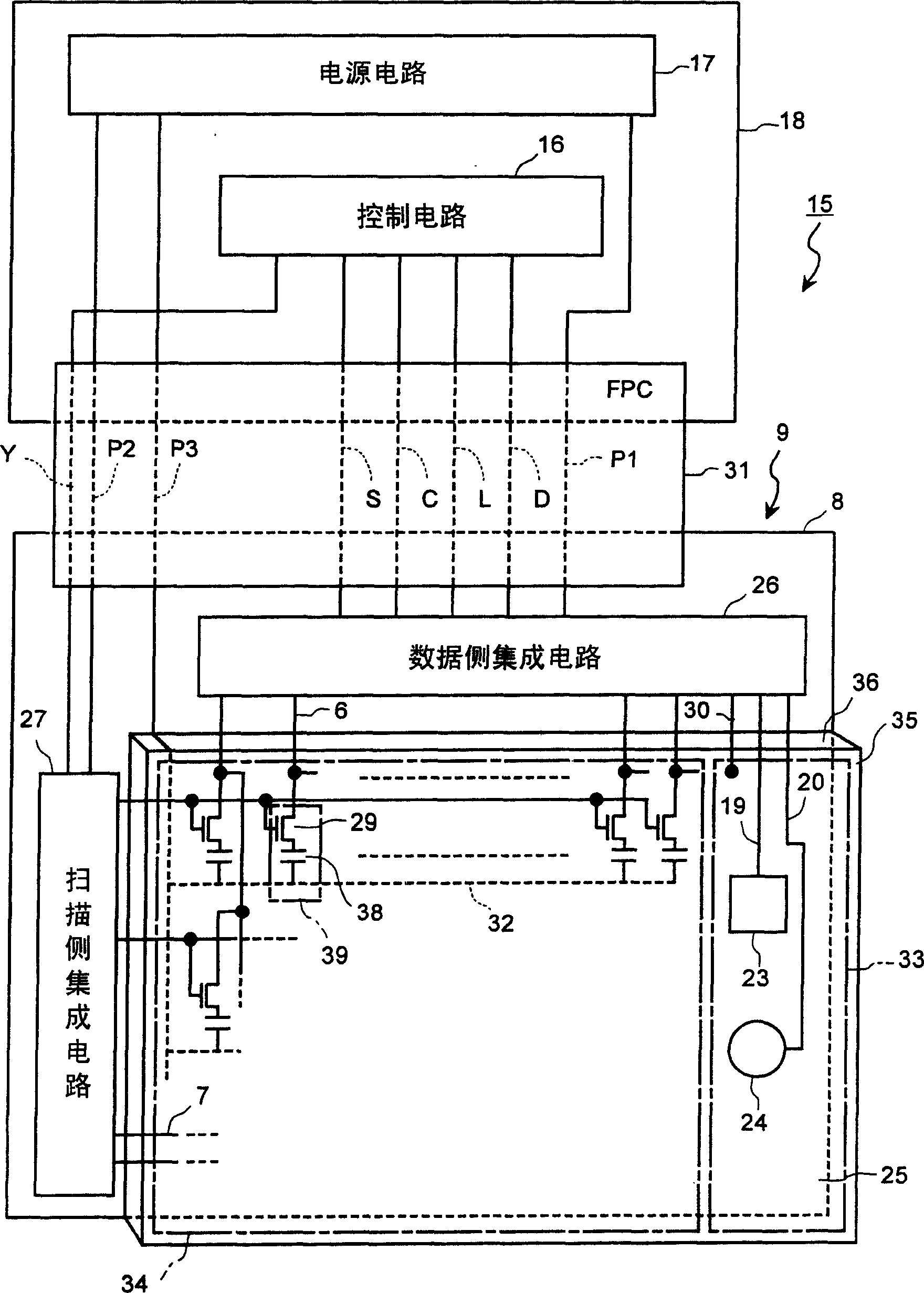
[0035] Typical embodiments of the liquid crystal device according to the present invention will be described below with reference to the accompanying drawings.

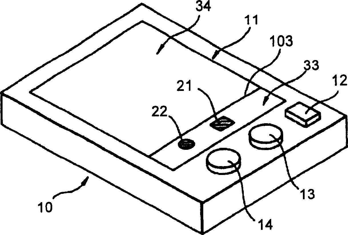
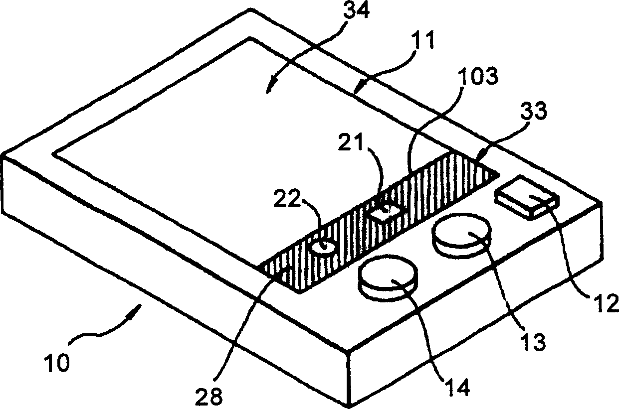
[0036] Figure 1A is a perspective view of a portable device 10 including a liquid crystal device according to an embodiment of the present invention. This liquid crystal display device has a display screen 11 . The portable device 10 includes: a power switch 12 , a first operation button 13 , and a second operation button 14 . Furthermore, the display screen 11 is divided by a boundary line 103 into a pictogram display area 33 for displaying a fixed image such as a pictogram, and a moving image display area 34 for displaying a moving image. In this example, the pictogram display area 33 includes a rectangular first pictogram Figure 21 and rounded second pictogram 22. These pictograms can be achieved by arranging segmented electrodes to the pictogram display area 33 Figure 21 and 22. For example, when the power...


PUM


Abstract

By using a potential difference between a common power source voltage and a data signal voltage required for driving an active liquid crystal display device, it is possible to display a pictogram without inputting a new signal to an opposing side and reduce a DC component in the pictogram drive by adjusting data signal gradation. A pictogram electrode of a pictogram display area is driven by using a part of a surplus output terminal of data driver for driving the moving picture display area. Thus, it is possible to provide a simple structure having a moving picture area and a pictogram area in a liquid crystal display device using a thin-film transistor (TFT) in which a common substrate is the entire surface electrode.

Description

technical field [0001] The invention relates to a liquid crystal display device having a moving image display area and a pictogram display area. More particularly, the present invention relates to a liquid crystal display device in which display electrodes of a moving image display area are driven by thin film transistors. Background technique [0002] In recent years, portable electronic devices using liquid crystal display devices, such as electronic organizers and cellular phones, have been widely used. Furthermore, electronic devices capable of displaying moving images have been popularized compared to previous electronic devices capable of displaying only still images. [0003] In such portable electronic devices, pictogram displays are becoming indispensable. The pictogram display is a display of a state of consumption of a battery serving as a driving source, a state of warning, and especially a state of an antenna level in a cellular phone. Furthermore, in order t...

Claims


Application Information

Patent Timeline
Patent Type & Authority Applications(China)
IPC IPC(8): G09G3/36
CPCG09G3/3648G09G2320/0204
Inventor 矢野敬和高桥和寿宫部光正关口金孝渡边贵彦石山敏昭池田真也
Owner CITIZEN WATCH CO LTD
Learn More