
An intelligent transformer operating and controlling device and its use

A technology for controlling devices and transformers, applied in measuring devices, circuit devices, emergency protection circuit devices, etc., can solve the problems of backward monitoring methods of transformer operation status, loss of industrial and agricultural production, inability to understand internal working status and structural status, etc. To achieve the effect of compact structure design, strong openness and low price

Inactive Publication Date: 2005-06-29
刘建南 +1
View PDF0 Cites 23 Cited by
  • Summary
  • Abstract
  • Description
  • Claims
  • Application Information

AI Technical Summary

Problems solved by technology

Because transformers are surrounded by high-voltage areas, there is a certain degree of danger. Therefore, transformers are generally installed in places far away from residents, and the internal working state and structural state of the transformer cannot be understood before the transformer fails. The monitoring means are very backward
Once a transformer failure occurs, it will inevitably lead to a stop of power supply, which in turn will bring losses to industrial and agricultural production.

Method used


Image

  • An intelligent transformer operating and controlling device and its use
  • An intelligent transformer operating and controlling device and its use
  • An intelligent transformer operating and controlling device and its use

Examples


specific Embodiment 1

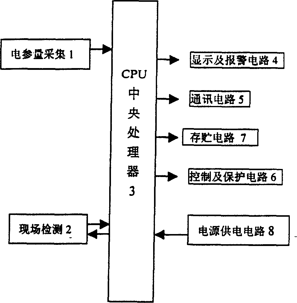
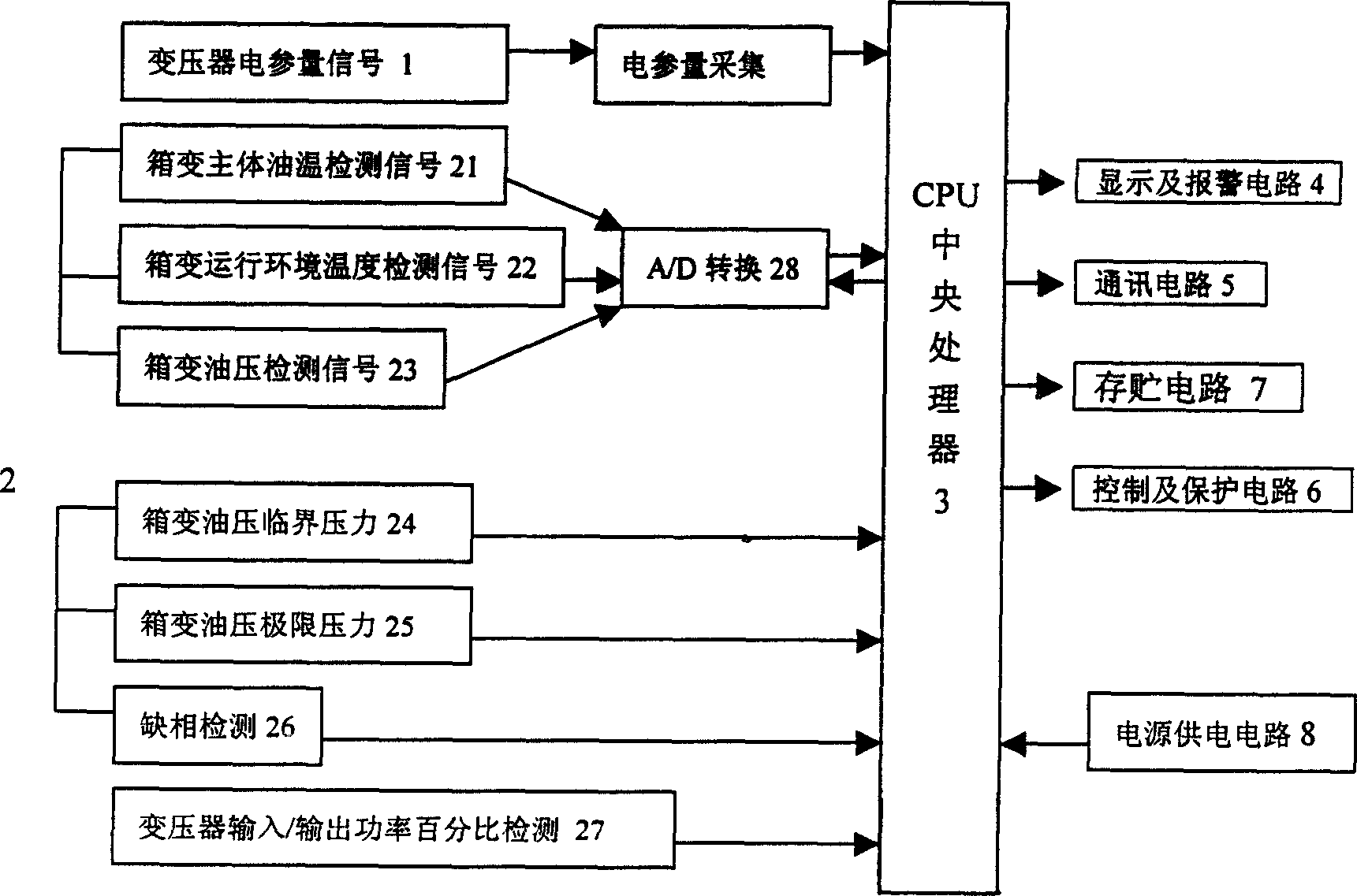
[0049] figure 1 , figure 2 , Figure 4 , Figure 5 , Figure 6 , Figure 7 and Figure 8 Embodiment 1 of the present invention is constituted.

[0050] From figure 1 It can be seen that this embodiment 1 is composed of electrical parameter acquisition circuit 1, on-site detection circuit 2, processing control circuit 3, display and alarm circuit 4, communication circuit 5, protection circuit 6, storage circuit 7 and power supply circuit 8. From figure 2 It can be seen that the on-site detection circuit 2 includes a transformer main body oil temperature detector 21, a transformer operating environment temperature detector 22, a transformer oil pressure detector 23, a transformer oil pressure critical pressure detector 24, a transformer oil pressure limit pressure detector 25, a transformer lack of Phase detector 26 and transformer input / output power percentage detection circuit 27, transformer main body oil temperature detector 21, transformer operating environment te...

specific Embodiment 2

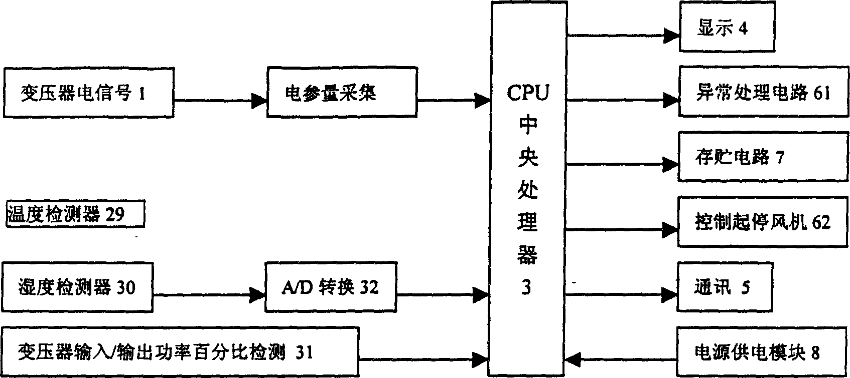
[0074] figure 1 , image 3 , Figure 4 , Figure 5 , Figure 6 , Figure 7 and Figure 8 Embodiment 2 of the present invention is constituted.

[0075] From image 3It can be seen that the characteristics of this embodiment are: the on-site detection circuit 2 includes a temperature detector 29, a humidity detector 30 and a transformer input / output power percentage detector 31, and the output terminals of the temperature detector 29 and the humidity detector 30 pass through the A / D The converter 32 is connected to the input end of the processing control circuit 3; the transformer input / output power percentage detector 31 respectively detects the input power and output power of the transformer, and the calculated percentage is sent to the input end of the processing control circuit 3; the protection circuit 6 includes abnormal The state processor 61 and the fan controller 62, the output end of the abnormal state processor 61 is connected to the control end of the abnorma...


PUM


Abstract

This invention relates to a transformer intelligent operation device and its usage characterizing comprising a parameter collection circuit, site test circuit, a process control circuit, a display and alarm circuit, a communication circuit, a protection circuit a storage circuit and a power supply circuit, in which, the output ends of the collection circuit and the site test circuit are connected with the input end of the control circuit, input ends of the display and alarm circuit, communication circuit and protection circuit are connected with the output end of the control circuit, output end of the communication can transmit signals via wire or wireless networks, the control ends of the load control switch or accessories of the transformer.

Description

technical field [0001] The invention relates to a transformer intelligent control device and its application, which is suitable for monitoring the operating status of American box-type transformers, dry-type transformers and box-type substations. It belongs to the technical field of transformer monitoring equipment. Background technique [0002] At present, the transformers used in the power system include dry-type transformers, combined transformers and American box-type transformers. American box-type transformers are more and more widely used. Since transformers are surrounded by high-voltage areas, there is a certain degree of danger. Therefore, transformers are generally installed in places far away from residents. The monitoring means are very backward. Once a transformer failure occurs, it will inevitably stop power supply, which in turn will bring losses to industrial and agricultural production. Therefore, the means of real-time monitoring of the working state o...

Claims


Application Information

Patent Timeline
IPC IPC(8): G01R31/00H02H5/00H02H5/04H02H5/08H02H7/04
Inventor 刘建南黄汝轩陈明凯胡燕红郭忠慧陈强
Owner 刘建南
Learn More