
Optical disc apparatus, clock signal generation method, program, and control apparatus

A technology of clock signal and optical disc device, applied in optical recording/reproduction, signal processing using self-timing code, rewritable optical disc, etc., can solve low access performance, low response speed of wobble clock generation circuit 300, etc. problem, to achieve the effect of improved access performance and increased loop gain

Inactive Publication Date: 2005-06-15
PANASONIC CORP
View PDF4 Cites 1 Cited by
  • Summary
  • Abstract
  • Description
  • Claims
  • Application Information

AI Technical Summary

Problems solved by technology

However, in this case, the response speed of the wobble clock generation circuit 300 is low, so that the wobble clock generation circuit 300 has low access performance

Method used


Image

  • Optical disc apparatus, clock signal generation method, program, and control apparatus
  • Optical disc apparatus, clock signal generation method, program, and control apparatus
  • Optical disc apparatus, clock signal generation method, program, and control apparatus

Examples


Embodiment 1

[0047] Hereinafter, Embodiment 1 of the present invention in which a clock signal is generated from a reproduced signal of the optical disc 101 will be described. On the optical disc 101, address information is recorded by MSK-modulating a wobble signal having a constant frequency.

[0048] figure 1 Represents the wobble signal before (I) and after (II) FM. Specifically, signal (I) is a wobble signal with a single frequency, which has not been frequency modulated. One period of signal (I) has 69 channel clock periods. Signal (II) is a wobble signal that has been MSK modulated. For example, the frequency of the MSK-modulated wobble signal is 1.5 times the frequency of the wobble signal before frequency modulation.

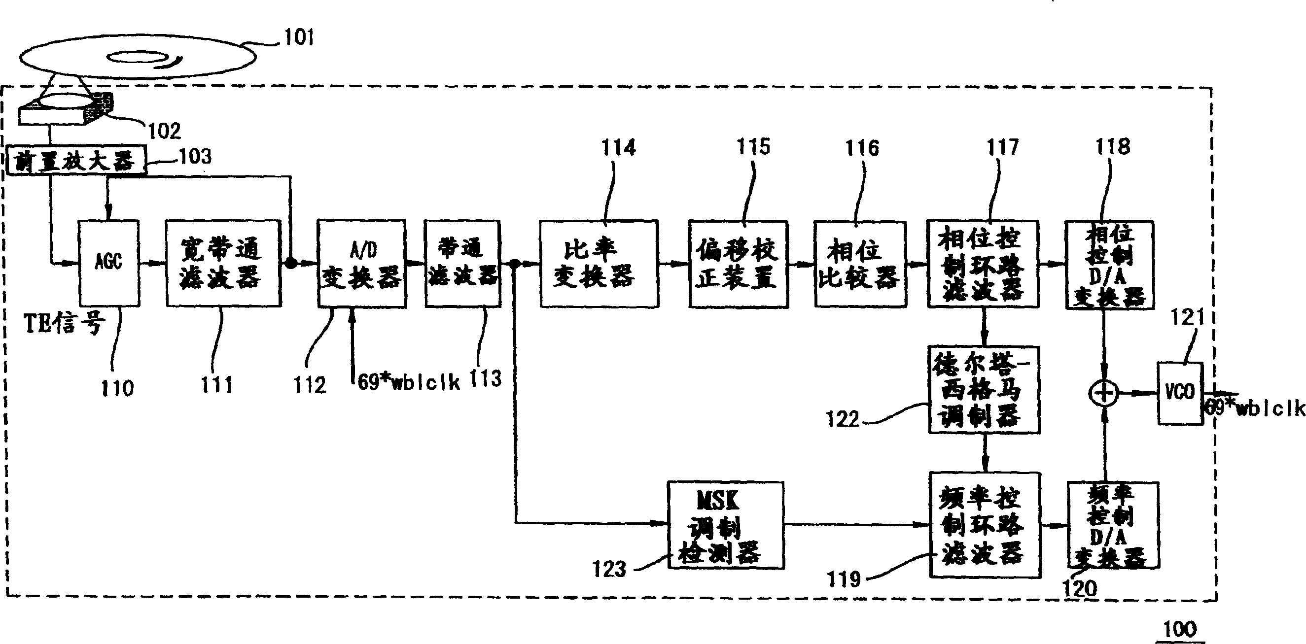
[0049] figure 2 An optical disc device 100 according to Embodiment 1 of the present invention is shown.

[0050] The optical disc device 100 is constructed so that the optical disc 101 can be inserted therein. The optical disc device 100 includes an optical...

Embodiment 2

[0085] Hereinafter, Embodiment 2 of the present invention in which a clock signal is generated from a reproduced signal of the optical disc 201 will be described. On the optical disc 201, address information is recorded by phase-modulating a wobble signal having a constant frequency.

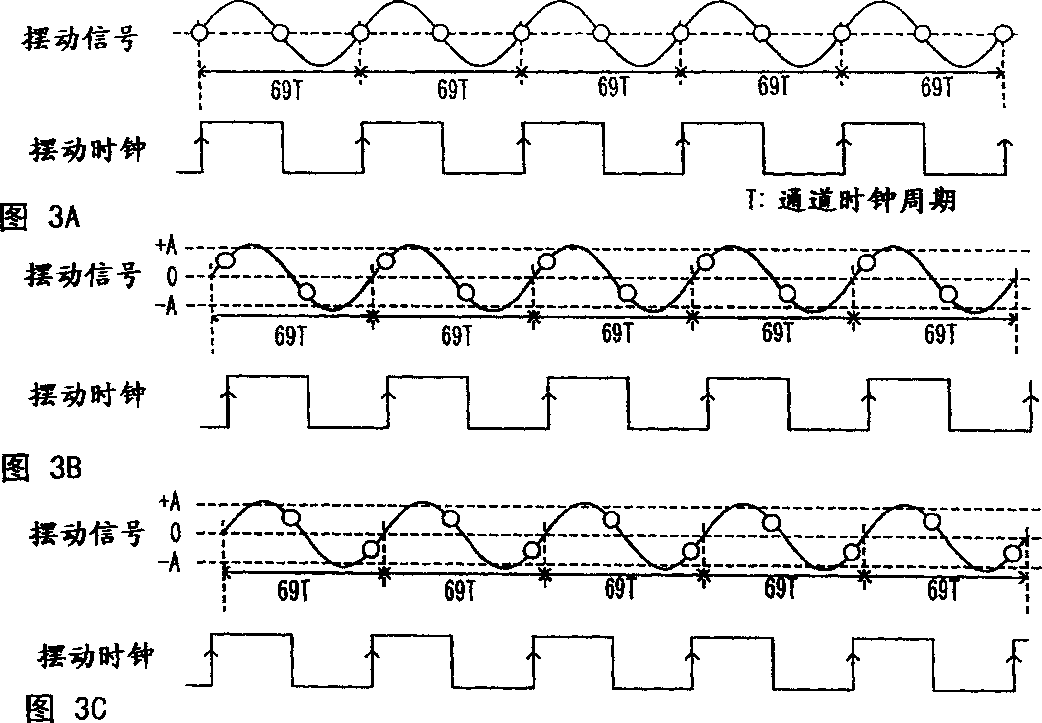
[0086] Figure 9 Represents the wobble signal before (III) and after (IV) phase modulation. Specifically, signal (III) is a single signal with a period 32 times the channel clock period. Signal (IV) is a wobble signal whose phase is reversed at two points.

[0087] A length corresponding to six periods of a wobble signal is compared between signal (III) and signal (IV). The length corresponding to six periods of a single signal (III) is 192 channel clock periods. The length corresponding to six periods of the wobble signal (IV) with two phase inversion points is 208 channel clock periods. This is because the interval of the rising edge is 48 channel clock periods in the part where the phase...


PUM


Abstract

The present invention provides an optical disc device comprising: a signal detection section for detecting a wobble signal from a reproduced signal of an optical disc; and a generation section for generating a clock signal synchronized with the wobble signal. The generation section includes: a first difference signal generation section for generating a first difference signal representing a difference between a frequency of the wobble signal and a frequency of the clock signal; a period detection section for a difference signal detecting a modulation period of said wobble signal; and an adjustment section for adjusting the frequency of said clock signal based on a predetermined signal other than said first difference signal during a modulation period, and The frequency of the clock signal is adjusted according to the first difference signal during one period.

Description

[0001] This non-provisional application claims priority under 35 U.S.C. §119(a) to Patent Application No. 2003-365653 filed in Japan on October 27, 2003, the entire contents of which are hereby incorporated by reference. technical field [0002] The present application relates to an optical disc device for detecting a wobble signal from a reproduced signal of an optical disc and generating a clock signal synchronized with the wobble signal. The present invention also relates to a method, program and device for generating a clock signal. Background technique [0003] Many recordable optical discs have recording grooves for tracking control of an optical head. The recording grooves meander at a predetermined period on the optical disc. In this case, the rotational speed of the optical disc can be detected from the reproduced signal of the optical disc. Based on the detected rotational speed, a clock is generated and the motor is controlled. [0004] Japanese Laid-Open Publi...

Claims


Application Information

Patent Timeline
Patent Type & Authority Applications(China)
IPC IPC(8): G11B5/09G11B7/00G11B7/09G11B20/10G11B20/14G11B27/24H03L7/08H03L7/085H03L7/091
CPCG11B20/1403G11B27/24G11B2220/216G11B2220/218G11B2220/2562G11B2220/2575H03L7/085H03L7/091
Inventor 中岛健宫下晴旬木村直浩
Owner PANASONIC CORP
Learn More