Press probe

A pressure, pressure sensor technology, applied in the direction of measuring fluid pressure, measuring fluid pressure through mechanical components, furnace, etc.

Inactive Publication Date: 2005-06-08
UNITED TECH CORP
View PDF3 Cites 3 Cited by
  • Summary
  • Abstract
  • Description
  • Claims
  • Application Information

AI Technical Summary

Problems solved by technology

[0003] However, there are still many possibilities for further improvement in this field

Method used


Image

  • Press probe
  • Press probe
  • Press probe

Examples


Embodiment Construction

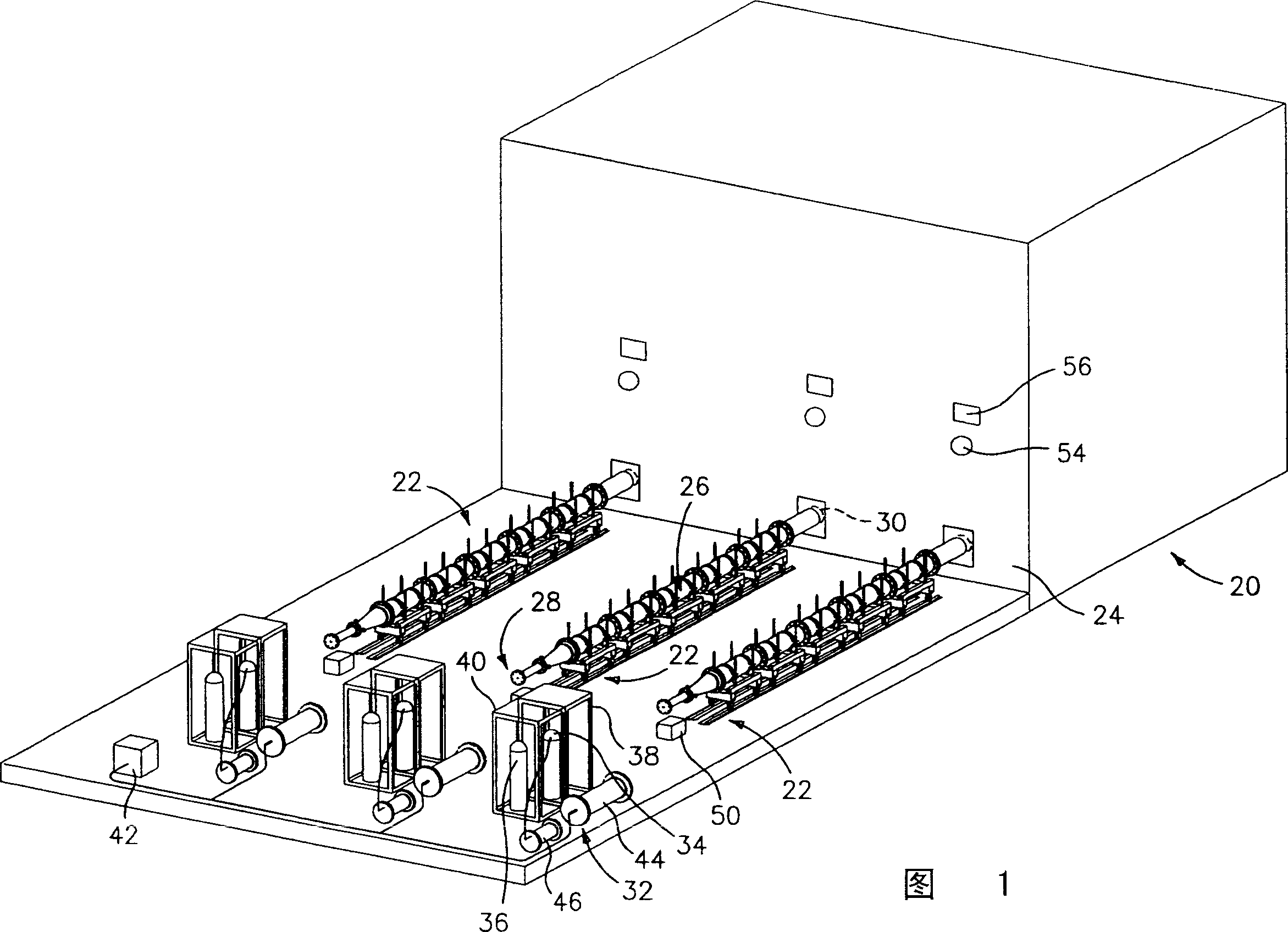
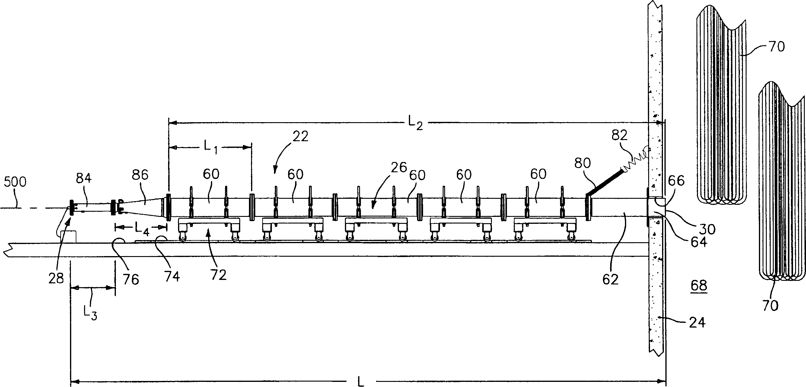
[0021] FIG. 1 shows a furnace 20 with exemplary three associated sootblowers 22 . In the embodiment shown, the shaft is formed in the form of a regular parallelepiped and the sootblowers are all associated with a single common wall 24 of the shaft and are arranged at the same height along the wall. Other configurations (eg, a single sootblower, one or more sootblowers on each of multiple levels, etc.) may also be used.

[0022] Each sootblower 22 includes an elongated combustion conduit 26 extending from an upstream distal end 28 remote from the furnace wall 24 to a downstream proximal end 30 proximate the wall 24 . Optionally, however, end 30 may be suitably located within the furnace. In operation of each sootblower, combustion of the fuel / oxidant mixture located within the conduit 26 begins near the upstream end (e.g., within the most upstream 10% of the conduit length) to generate a detonation wave which, along with the associated combustion gases It is emitted from the ...


PUM

PropertyMeasurementUnit
Lengthaaaaaaaaaa
Maximum horizontal sizeaaaaaaaaaa

Abstract

Pressure probe methods and apparatus are disclosed. An exemplary probe includes a body having an outer surface with a forwardly converging nose. A passageway extends between the first port in the body and the pressure sensor. The support member holds the body in the operative position. A cooling fluid circuit extends at least partially through the support member and the body. Pressure probes can be used in combination with detonation cleaning equipment.

Description

technical field [0001] The present invention relates to industrial equipment. More particularly, the present invention relates to detonation cleaning of industrial equipment. Background technique [0002] Surface fouling is a major problem in industrial equipment. Such equipment includes furnaces (coal, oil, waste, etc.), boilers, gasifiers, reactors, heat exchangers, and the like. Typically, such equipment includes vessels containing internal heat transfer surfaces that are susceptible to accumulation of particles such as soot, ash, minerals and other combustion products and by-products, more integrally agglomerated such as slag and / or dirt, etc. Dirt forms. This buildup of particles can gradually impede equipment operation, reduce efficiency and throughput, and possibly cause damage. Therefore, it is very necessary to clean the equipment and the cleaning work of the equipment needs to take into account many relevant factors. Often, direct access to dirt-laden surfaces...

Claims


Application Information

Patent Timeline
IPC IPC(8): B08B7/00B08B9/08F22B37/48F27D19/00F27D21/00F27D25/00F28G7/00F28G11/00F28G13/00F28G15/00F28G15/02
CPCB08B7/0007B08B9/08F27D19/00F27D21/00F27D25/006F28G7/00F28G7/005F28G15/00F28G15/02B08B9/02F28G1/16F28G11/00
Inventor D·W·肯德里克M·J·阿尼奥J·R·小霍赫施泰因
Owner UNITED TECH CORP
Why Eureka
Try Eureka