
System for protecting a vehicle from a mine

a vehicle and system technology, applied in the direction of shields, roofs, manufacturing tools, etc., can solve the problems of low or no effect of higher ground clearance, vehicle itself being propelled upward, and cylindrical columns of sand or soil

Inactive Publication Date: 2012-04-03
FORCE PROTECTION TECH
View PDF65 Cites 59 Cited by
  • Summary
  • Abstract
  • Description
  • Claims
  • Application Information

AI Technical Summary

Benefits of technology

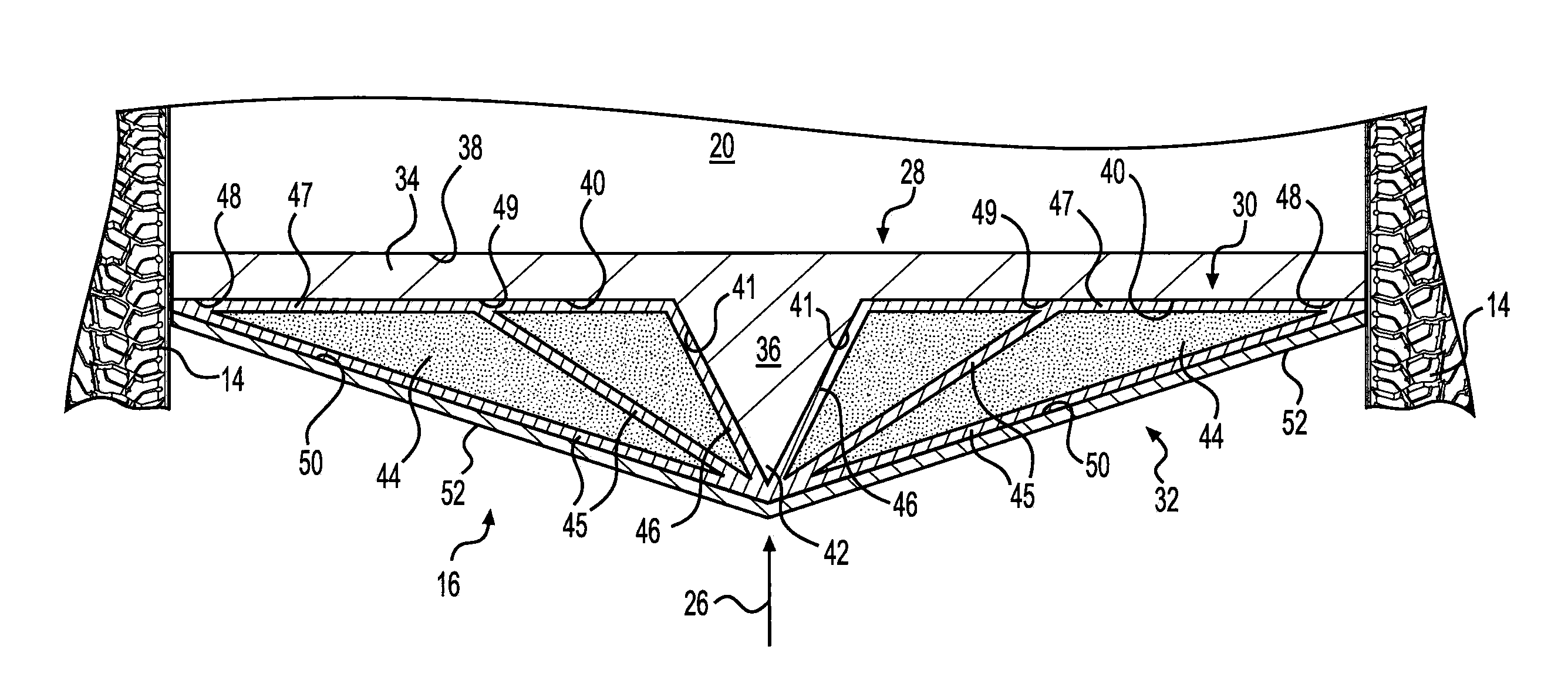
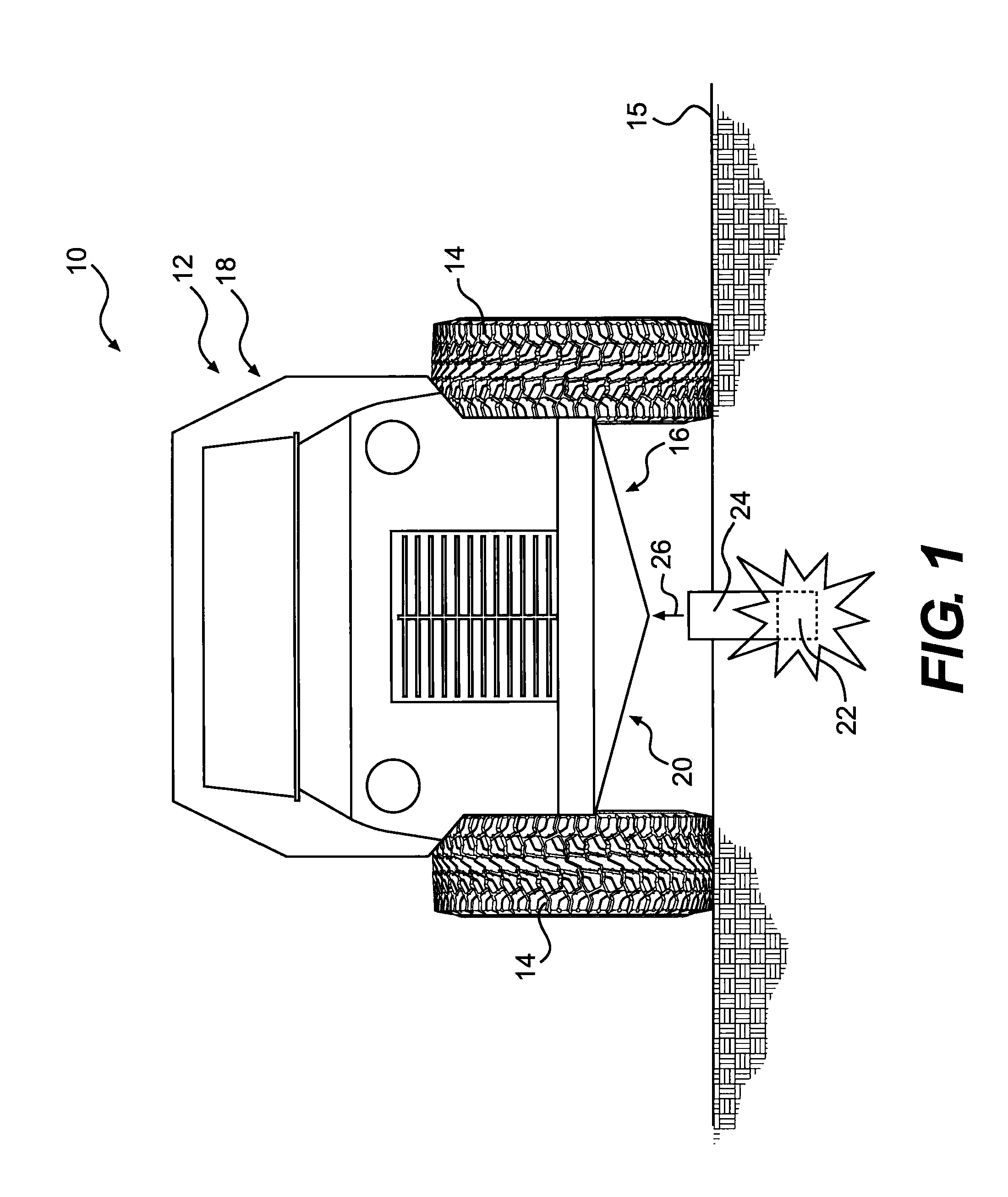
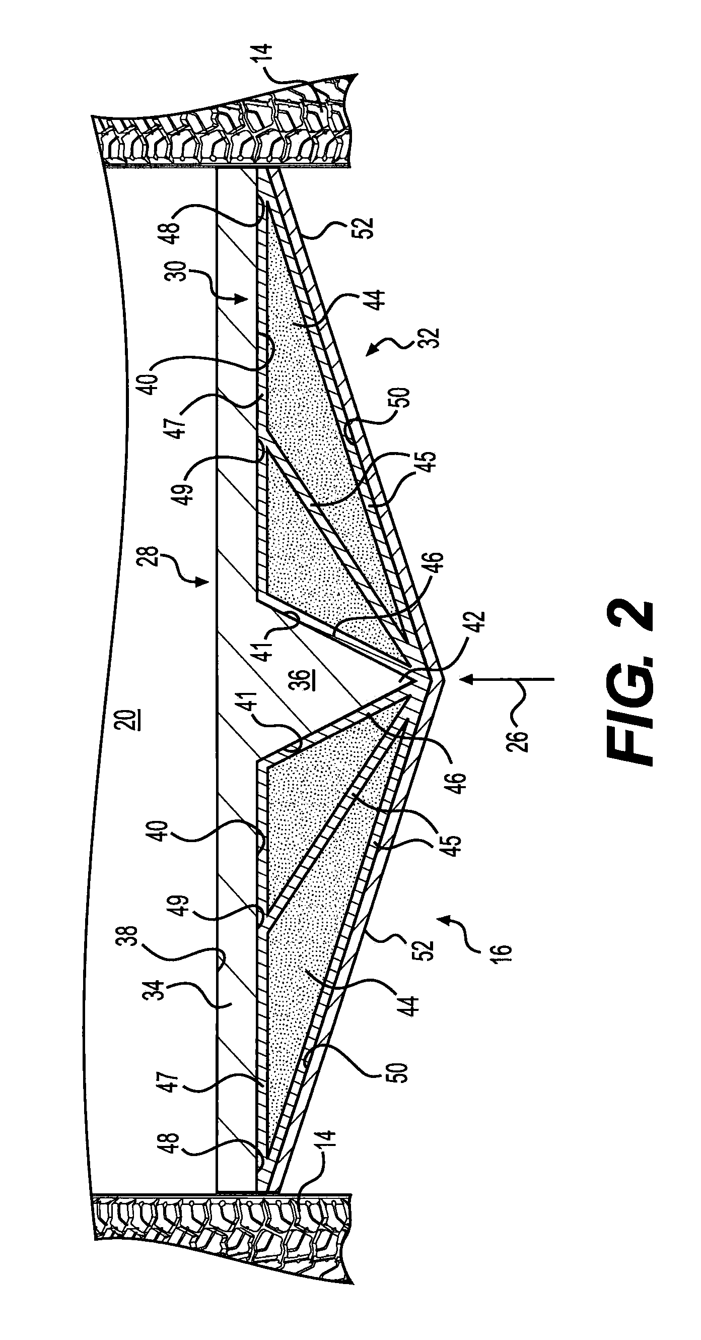
"The present disclosure is about a system to protect a vehicle from a mine that is located underground. The system includes a layer of material that is placed on top of the vehicle's underbody and a layer of material that is placed on top of the first layer. The second layer is made of a material that can withstand shock waves better than the first layer. The system also has an exterior layer that is placed on top of the first and second layers. This layer is angled in relation to the first layer to deflect the ejecta from the expected trajectory. The technical effect of this system is to protect the vehicle from the impact of the ejecta and minimize damage to the vehicle in case of a detonation."

Problems solved by technology

Additionally, the energy of the material and the blast being transferred to that surface may cause the vehicle itself to be propelled upward, and in some cases, leave the surface on which the vehicle runs.
However, when a traditional mine is buried beneath the ground, such as, for example, under sand or soil, the blast usually results in a cylindrical column of sand or soil.
However, because very little energy actually dissipates from the soil ejecta before it contacts the vehicle, the higher ground clearance has little or no effect.
Therefore, a high ground clearance may only serve to raise the center of gravity of the vehicle.
This may cause the vehicle to have a higher center of gravity, and may reduce the maneuverability of the vehicle.
If the bottom of the vehicle is not flat, energy and blast material impulses may be less efficiently transferred to the body of the vehicle.

Method used


Image

  • System for protecting a vehicle from a mine
  • System for protecting a vehicle from a mine
  • System for protecting a vehicle from a mine

Examples


Embodiment Construction

[0001]1. Field of the Invention

[0002]The present disclosure relates to a system for protecting a vehicle from a mine.

[0003]2. Background of the Invention

[0004]Conventional armored motor vehicles attempt to moderate the effect of mines and explosive devices by using armor of a thickness that will not be penetrated by soil, rocks or the like, or by the blast from such a mine or explosive device. Such vehicles generally have bottom surfaces parallel to the surface on which they ride.

[0005]When such vehicles detonate an anti-vehicle mine below the vehicle, a penetrator and / or debris above the mine is propelled upward. If the bottom of the vehicle is flat and parallel to the ground, much of the energy of the mine and any material propelled by it may hit the bottom surface perpendicular to its surface. As a result, the energy of the material and the blast is most efficiently transferred to that surface and the probability that the armor bottom will be defeated and breached is maximized. A...


PUM

PropertyMeasurementUnit
angleaaaaaaaaaa
angleaaaaaaaaaa
shock wave transmission velocityaaaaaaaaaa

Abstract

In one aspect, the present disclosure is directed to a system for protecting a vehicle from a mine. Upon detonation the mine may yield ejecta having an expected trajectory. The system has a first layer of material disposed outside of an underbody of a hull of the vehicle. The first layer includes a base disposed in a direction substantially parallel to the underbody and a protrusion that narrows as it extends away from the base in a direction opposing the expected ejecta trajectory. The system also has a second layer including a material having a shock wave transmission velocity that is higher than a shock wave transmission velocity of the material of the first layer. The system further has an exterior layer substantially covering the first and second layers, and the exterior layer has an exterior surface that faces away from the underbody and toward the expected ejecta trajectory.

Description

DESCRIPTION OF THE INVENTION[0001]1. Field of the Invention[0002]The present disclosure relates to a system for protecting a vehicle from a mine.[0003]2. Background of the Invention[0004]Conventional armored motor vehicles attempt to moderate the effect of mines and explosive devices by using armor of a thickness that will not be penetrated by soil, rocks or the like, or by the blast from such a mine or explosive device. Such vehicles generally have bottom surfaces parallel to the surface on which they ride.[0005]When such vehicles detonate an anti-vehicle mine below the vehicle, a penetrator and / or debris above the mine is propelled upward. If the bottom of the vehicle is flat and parallel to the ground, much of the energy of the mine and any material propelled by it may hit the bottom surface perpendicular to its surface. As a result, the energy of the material and the blast is most efficiently transferred to that surface and the probability that the armor bottom will be defeated ...

Claims


Application Information

Patent Timeline
Patent Type & Authority Patents(United States)
IPC IPC(8): F41H7/02
CPCF41H7/042Y10T29/49716
Inventor JOYNT, VERNON P.
Owner FORCE PROTECTION TECH
Learn More