Combustion device for circular combustion chamber in a gas turbine plant

一种环形燃烧室、燃气轮机的技术,应用在使用块状燃料和气态燃料的燃烧、使用液体燃料和气态燃料的燃烧、使用块状燃料和液体燃料的燃烧等方向,能够解决结构费事、燃烧器更换过程费时间等问题

Inactive Publication Date: 2005-05-11
ANSALDO ENERGIA SWITZERLAND AG
View PDF0 Cites 2 Cited by
  • Summary
  • Abstract
  • Description
  • Claims
  • Application Information

AI Technical Summary

Problems solved by technology

[0005] The disadvantage of this known double-row burner arrangement is that it must be possible to access the burner via corresponding manholes for changing the burner, which is structurally complex
Disadvantages of this solution are also the time-consuming burner replacement process
However, providing an access opening in the turbine casing through which the burner can be easily removed outwards raises questions regarding the mechanical integrity of the turbine casing

Method used


Image

  • Combustion device for circular combustion chamber in a gas turbine plant
  • Combustion device for circular combustion chamber in a gas turbine plant

Examples


Embodiment Construction

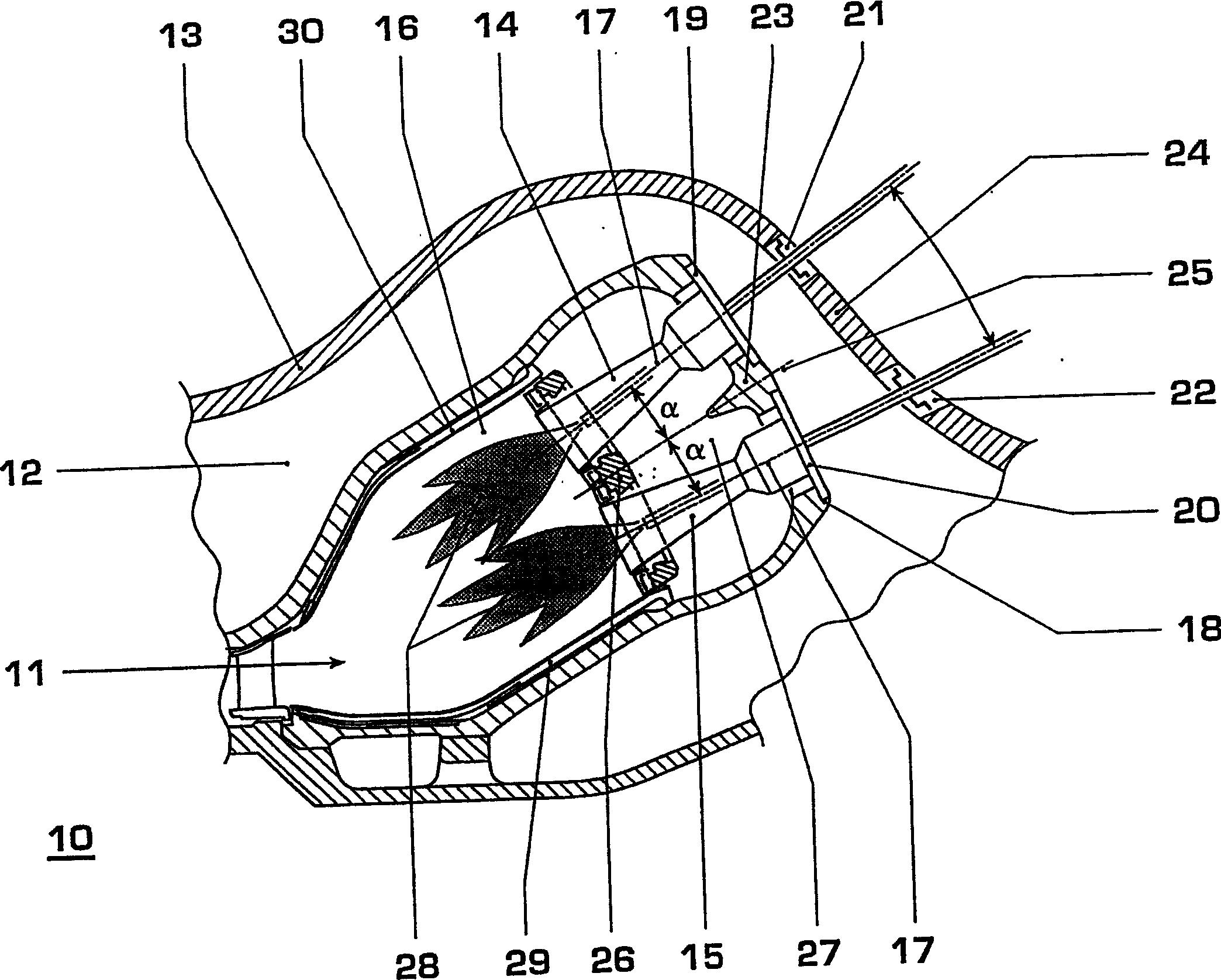
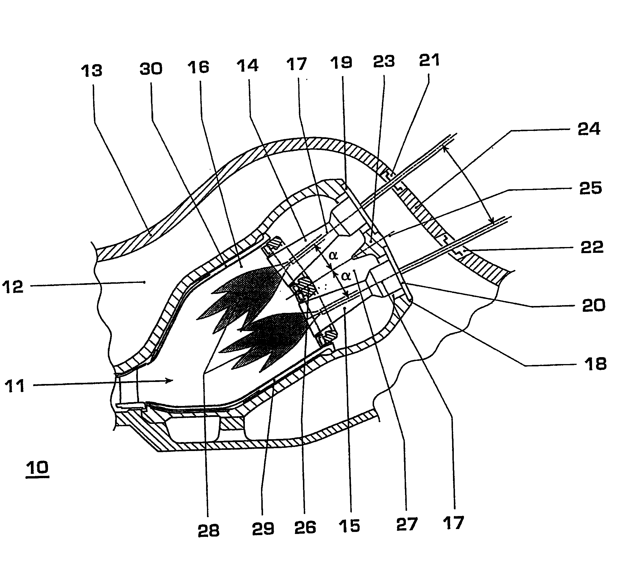
[0013] The drawing shows a section through a combustion chamber of a gas turbine with a burner arrangement according to a preferred embodiment of the invention. For the gas turbine 10, only a part above the axis of the gas turbine is shown, the gas turbine has a gas turbine outer casing 13, which surrounds a pressurized air space 12 filled with compressed air and a space between the compressor part and the turbine. Combustion chamber 11 between sections. The combustion chamber 11 is formed annularly with respect to the turbine axis. In its entry-side top chamber 27 are accommodated two rows of superposed burners 14 , 15 , which are designed in a known manner as double-cone burners and open into the combustion chamber 11 . The burners 14, 15 form a coaxial ring similar to that described in Figure 3 of EP-A1-0597138 (but with a different offset). The top chamber 27 is closed to the outside (towards the compressed air space 12 ) by a combustion chamber housing 18 . Correspondi...


PUM


Abstract

In a burner arrangement for an annular combustion chamber (11) of a gas turbine (10), a plurality of burners (14, 15) are each arranged in pairs radially one above the other on a concentric ring. In this burner arrangement, the two burners (14, 15) of a burner pair are aligned offset from parallel in such a way that their burner axes (17) approach each other gradually in the direction of flow. This increases the mechanical integrity of the gas turbine housing and optimizes the operation of the combustion chamber.

Description

technical field [0001] The present invention relates to the technical field of gas turbines, in particular to a burner device for an annular combustion chamber of a gas turbine according to the preamble of claim 1 . [0002] One such burner arrangement is known, for example, from EP-A1-0597138. Background technique [0003] Currently, annular low NO X The (EV-)combustion chamber (EV=Environmental) is a proven technology (see for example F.Joos et al. "Development of the sequential combustion system for the GT24 / GT26 gas turbine family", ABB Review, 1998 No. 4 , pp. 4-16). In such gas turbines / combustion chambers, the burners can be removed through corresponding access openings in the outer shell of the gas turbine. [0004] Other gas turbines (for example the applicant's GT13E type) have a double-row burner arrangement in an annular combustion chamber, as for example in the appendix of the document EP-A1-0597138 mentioned at the beginning. figure 1 and as indicated in 3....

Claims


Application Information

Patent Timeline
Patent Type & Authority Applications(China)
IPC IPC(8): F23C5/08F23R3/50
CPCF23R3/283F23R3/50
Inventor 彼得·赫拉夫斯特凡·奇伦赫尔玛·文德勒
Owner ANSALDO ENERGIA SWITZERLAND AG
Why Eureka
Try Eureka