High frequency module and communication device

A high-frequency module, frequency characteristic technology, used in high-frequency matchers, transmission systems, electrical components, etc., can solve problems such as large-scale and high-cost, to prevent short circuits, improve air tightness, and prevent inflow of gas. Effects on the dense space side

Inactive Publication Date: 2005-04-13
KYOCERA CORP
View PDF0 Cites 23 Cited by
  • Summary
  • Abstract
  • Description
  • Claims
  • Application Information

AI Technical Summary

Problems solved by technology

[0008] However, when each dedicated part is used and mounted on the board separately, it leads to an increase in the size and cost of the equipment

Method used


Image

  • High frequency module and communication device
  • High frequency module and communication device
  • High frequency module and communication device

Examples


Embodiment Construction

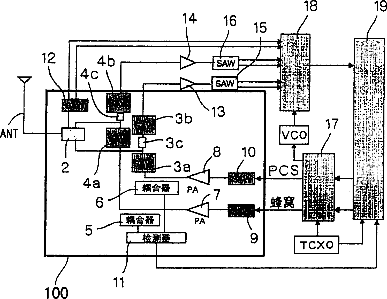
[0091] figure 1 A block diagram showing a high-frequency signal processing circuit of a dual-band system used in a mobile communication device.

[0092] In this dual-band mode, it is composed of two transmitting and receiving systems having frequency bands of 800MHz for cellular method and 1.9GHz for PCS method, and one receiving system having GPS receiving band of 1.5GHz for positioning function using GPS (Global Positioning System) .

[0093] figure 1 Among them, ANT is an antenna, 2 is an LC duplexer including a low-pass filter and a high-pass filter for frequency division, 3a is a SAW filter for separating the transmission system of the 1.9GHz band, and 3b is a SAW filter for separating the receiving system 4a is a SAW filter for separating the transmission system of the 800 MHz band, and 4b is a SAW filter for separating the reception system.

[0094] In addition, 12 is a SAW filter through which the GPS signal taken in from the above-mentioned LC duplexer 2 passes. ...


PUM


Abstract

A high-frequency module, on the surface of a multilayer substrate (23) is equipped with a transmission filter (3a, 4a), a reception filter (3b, 4b), a high-frequency power amplifier circuit (7, 8), etc. An integrated circuit (3c, 4c) is inserted between the input terminal of the filter for reception and the output terminal of the filter for transmission. Inside the multilayer substrate (23), distributed constant lines and the like are formed as constituent parts of the above-mentioned integrated circuit (3c, 4c). The entire high-frequency module can be miniaturized.

Description

field of invention [0001] The present invention relates to a high-frequency module integrally constituting a high-frequency power amplifier circuit, a band-pass filter, a high-frequency wave division circuit, etc., and a communication device such as a mobile phone equipped with the high-frequency module. Background technique [0002] In recent years, popularization of mobile phones is progressing. Attempts to improve the functions and services of mobile phones. [0003] In such a mobile phone, a high-frequency signal processing circuit necessary for the configuration of each transmitting and receiving system is mounted on a substrate. [0004] In a general configuration of a conventional high-frequency signal processing circuit, a transmission filter and a reception filter are provided for switching between a reception signal input from an antenna and a transmission signal fed to the antenna. [0005] The radio signal coming in from the antenna is input to the receiving fi...

Claims


Application Information

Patent Timeline
Patent Type & Authority Applications(China)
IPC IPC(8): H01P1/20H03H9/15H03H9/72H04B1/06H04B1/40H05K1/00H05K1/02H05K1/16
CPCH01L2924/19041H03H9/725H04B1/0057H04B1/52H05K1/0237H05K1/0298H05K1/16H01L2224/32225H01L2224/48227H01L2224/73265H01L2924/01019H01L2223/6677H01L2224/16225H01L2924/15311H01L2224/45144H01L2924/3011H01L2924/30107H01L2924/1461H01L2924/1305H01L23/66H01L25/16H01L2924/15192H01L24/73H01L2224/16235H01L2924/14H01L2224/05573H01L2224/05568H01L2924/19105H01L2924/00012H01L2924/00H03H9/15H03H9/72H04B1/40
Inventor 黑木博森博之北泽谦治宫胁义宏
Owner KYOCERA CORP
Why Eureka
Try Eureka