
Bus capaeitance current weakening method and device

A bus capacitance and current technology, applied in the direction of output power conversion devices, electrical components, conversion equipment with intermediate conversion to AC, etc.

Active Publication Date: 2005-03-23
DELTA ELECTRONICS INC
View PDF0 Cites 0 Cited by
  • Summary
  • Abstract
  • Description
  • Claims
  • Application Information

AI Technical Summary

Problems solved by technology

This method also has a certain effect, but if the system runs in a high temperature environment, this method also has certain limitations

Method used


Image

  • Bus capaeitance current weakening method and device
  • Bus capaeitance current weakening method and device
  • Bus capaeitance current weakening method and device

Examples


Embodiment Construction

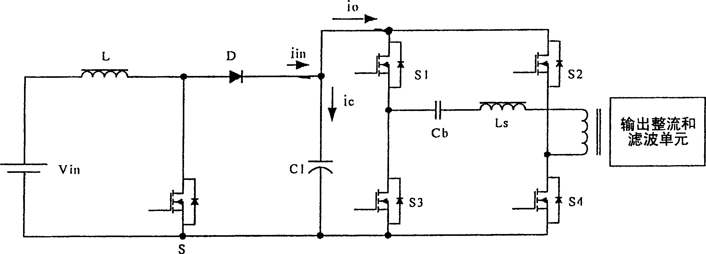
[0033] In order to reduce the capacitor current of the direct current bus, the present invention improves the design of the multi-level converter from the perspective of the topology of the main circuit. A main circuit architecture in which the front stage adopts a frequency multiplication power factor correction circuit and the latter stage adopts a phase-shifted full-bridge circuit is proposed. Such as Figure 4 shown. The subsequent stage of the system employs and figure 1 The same circuit, the main difference is that the power factor correction circuit of the previous stage has been improved, and the original single structure has been changed into a double structure. Vin in the left part of the figure, inductors La, Lb, power switch components Sa, Sb, power secondary components Da, Db and bus capacitor C1 constitute a power factor correction unit. La, Sa, Da correspond to Lb, Sb, Db respectively, each forming an independent unit. Its general working principle has two p...


PUM


Abstract

The invention discloses a dipolar structure with dc bus. The preceding stage is power factor correcting circuit (PFC circuit), while the back stage is the direct current-direct current transfer circuit. The dc bus is between the two poles. The preceding stage transforms the direct current into the alternating current and infuses it into the dc bus, while the direct current-direct current transfer unit of the back stage draws the current out of the dc bus. We need to connect a generatrix capacitor parallelly to connect the two stages, only make the alternating current (that is the generatrix capacitor current) pass through it to balance the instantaneous power imbalance between the two stages. The invention provides a method of weakening the generatrix capacitor current and its device.

Description

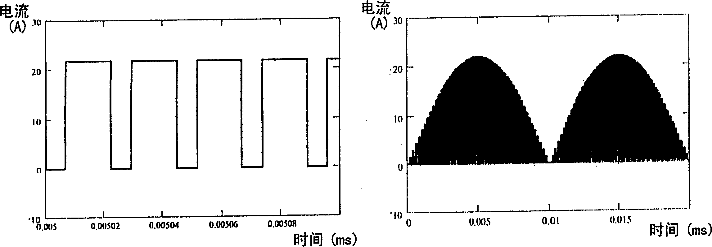
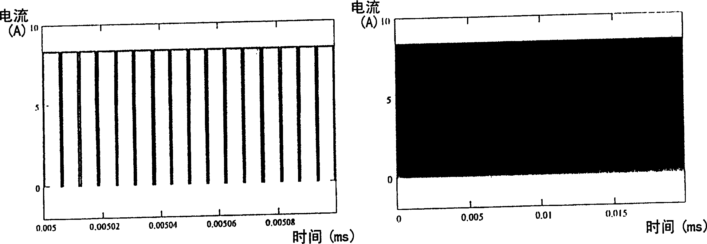
technical field [0001] The invention relates to a bus capacitance current weakening method and device, in particular to a DC-DC conversion circuit with the bus capacitance current weakening effect. Background technique [0002] In power electronic converters, considering the reliability of the circuit and the ease of production, a multi-level circuit structure is often used. Almost all multi-level structures have a DC bus (DC Bus). A large electrolytic capacitor is often connected in parallel on the DC bus. For example, in a common communication power supply, a two-stage structure with a DC bus is usually used, the front stage is usually a power factor correction circuit (PFC circuit), and the rear stage is a DC-DC conversion circuit. Between the two stages is the so-called DC bus. The front stage converts AC power into DC and injects it into the DC bus, and the latter DC-DC conversion unit draws current from the DC bus. When the circuit works in a steady state, the avera...

Claims


Application Information

Patent Timeline
IPC IPC(8): H02M1/14H02M3/28
CPCY02P80/10
Inventor 应建平张庆友邱爱斌刘腾郭兴宽曾剑鸿
Owner DELTA ELECTRONICS INC
Learn More