
Metal ion source

A metal ion source and cathode technology, applied in the field of ion sources

Inactive Publication Date: 2005-03-16
XI AN JIAOTONG UNIV
View PDF0 Cites 12 Cited by
  • Summary
  • Abstract
  • Description
  • Claims
  • Application Information

AI Technical Summary

Problems solved by technology

Now the user’s request is that a source can generate gas, metal and other element ions, and a large output is required to meet the needs of ion implantation modification. The traditional design method cannot meet the requirements, so it is necessary to design a new structure. source of ion

Method used


Image

  • Metal ion source

Examples


Embodiment Construction

[0015] Accompanying drawing is the specific embodiment of the present invention;

[0016] Below in conjunction with accompanying drawing, structural principle and working principle of the present invention are further described:

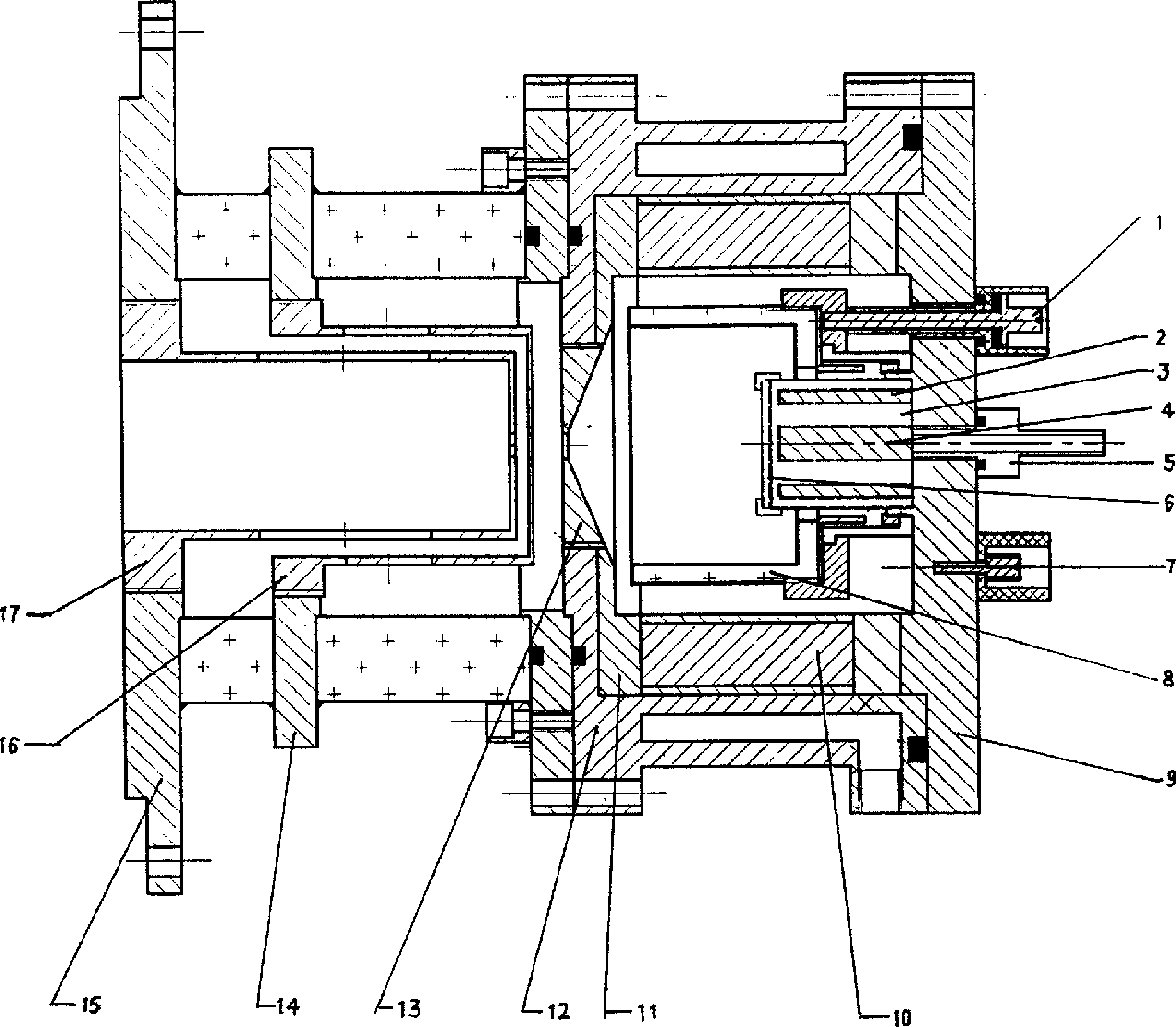
[0017] Shown with reference to accompanying drawing, a kind of metal ion source comprises base 9, is fixed with air inlet nozzle 5 on base 9, is connected with cathode 3 on air inlet nozzle 5, cathode 3 is fixed on base 9, is provided with on cathode 3 The air hole that can communicate with the air inlet nozzle 5, the cathode 3 is connected with the anode 8, and the magnet 10 is arranged outside the anode 8, and the upper end of the magnet 10 is fixed by the installation plate 11, and the installation plate 11 is fixed on the installation cylinder 12, and the installation cylinder 12 Set outside the magnet 10, the lower end of the magnet 10 and the installation cylinder 12 are fixed on the base 9, and the extraction grid 13 is installed on the instal...


PUM


Abstract

The invention relates to a metal ion source capable of promoting high-density metallic element ion. In the invention auxiliary cathode is added to the cathode, and protrudes in the anode region, and constitutes a discharge chamber with anode. Circular magnet and ferromagnet is mounted under the auxiliary cathode, ferromagnet placing in circular magnet, and connected to cathode. Auxiliary cathode is made of needed metal element, when a certain metal element is needed, auxiliary cathode and magnet prepared from the material are mounted to constitute magnetron sputtering source, so the auxiliary cathode enlarge the metal element sputtering yield, protect the original cathode, prolong the ion source life time. When gas ion is needed, it is OK that circular magnet and ferromagnet under the auxiliary cathode be removed. The ion sputtering source can satisfy the needs of gas ion or metal ion.

Description

technical field [0001] The invention relates to an ion source, which belongs to the surface modification technology of ion beam materials; in particular, it relates to a metal ion source capable of increasing high-density metal element ions. Background technique [0002] Ion implantation technology is widely used in the research of material surface modification and the fabrication of microelectronic devices, so ion implantation technology is a very important application technology. The core component of ion implantation technology is the ion source that generates ions. When the various ions generated by the ion source pass through the electric field, they obtain high energy, and then inject these high-energy ions into the sample to form a new structure on the surface of the sample, so as to achieve the purpose of material surface modification and the formation of new devices. [0003] There are various ion sources for obtaining different implant elements. The most commonly...

Claims


Application Information

Patent Timeline
IPC IPC(8): C23C14/48H05H1/16
Inventor 赵玉清沈伯礼赵鑫朱克志李冬梅
Owner XI AN JIAOTONG UNIV
Learn More