
Plunger type automatic regulating pressure anti-lock braking device for automobile

An automatic pressure adjustment, plunger type technology, applied in the direction of brakes, etc., can solve the problem that the brake pressure cannot be automatically adjusted

Inactive Publication Date: 2005-03-16
任亮
View PDF0 Cites 1 Cited by
  • Summary
  • Abstract
  • Description
  • Claims
  • Application Information

AI Technical Summary

Problems solved by technology

Although the hydraulic plunger type anti-lock device is suitable for passengers and trucks under 8 tons and cars with a displacement greater than 3.0L, it cannot automatically adjust the brake pressure for heavy-duty, especially super-heavy vehicles.

Method used


Image

  • Plunger type automatic regulating pressure anti-lock braking device for automobile
  • Plunger type automatic regulating pressure anti-lock braking device for automobile

Examples


Embodiment Construction

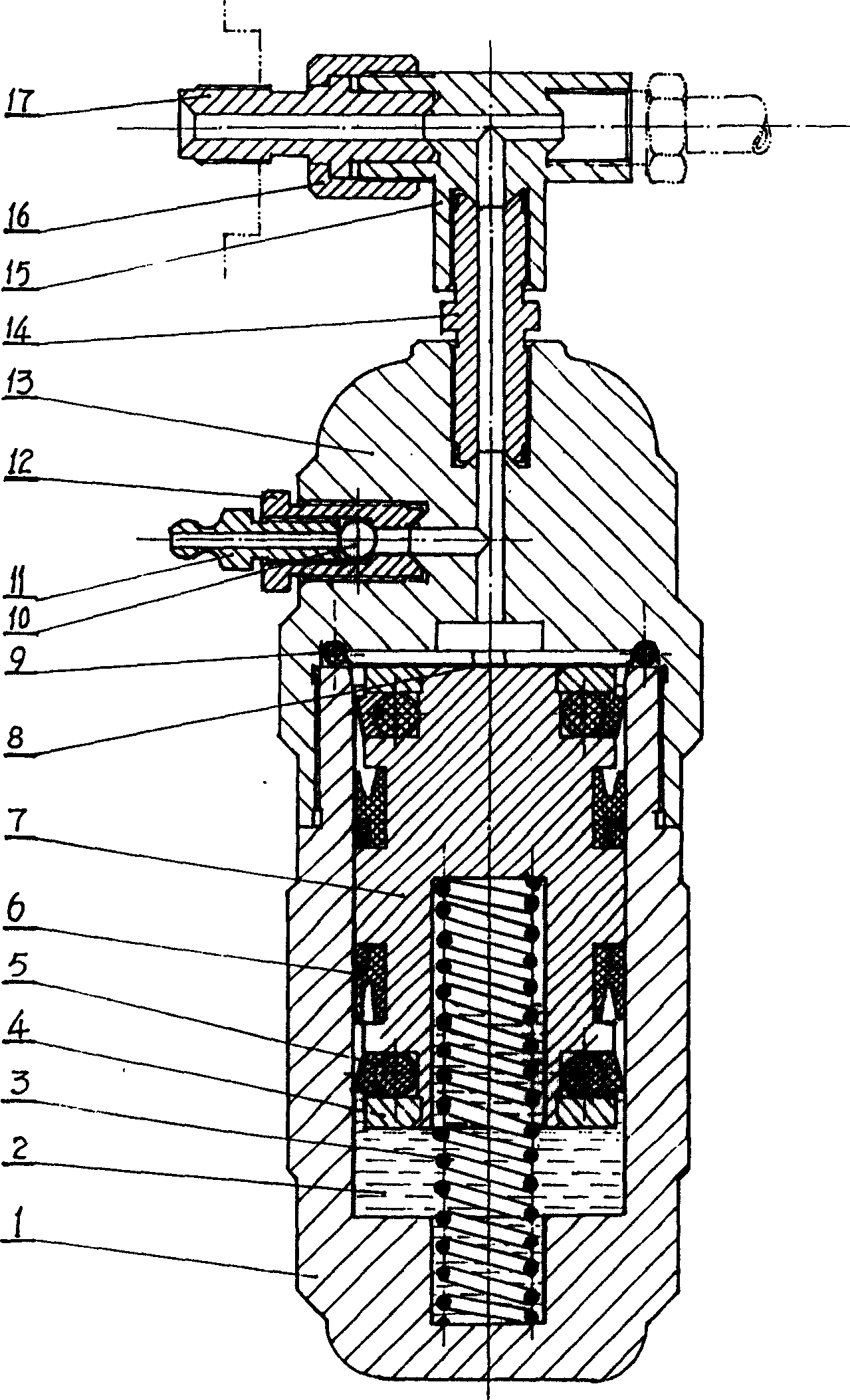
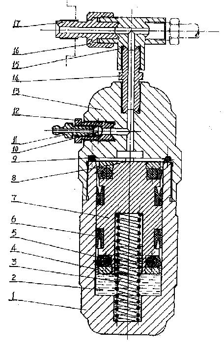
[0010] The hydraulic plunger type automatic pressure-regulating automobile anti-lock device includes a three-way valve body, a valve body 13, and an air release nozzle. The three-way valve body is fixedly connected to the valve body through a joint 14, and one side of the valve body is fixedly connected to the air release nozzle 11; The valve body is fixedly connected with the oil cylinder 1 to form an inner cavity, which is sealed by an "O" type sealing ring 9; the inner end of the valve body 13 is provided with a "cross-shaped" oil (gas) groove; on the end surface of the "cross-shaped" oil (gas) groove Press the filter screen 8 tightly; a sliding plunger 7 is installed in the oil cylinder; the upper and lower ends of the plunger are fixedly connected to the Sierra oil seal 5, and the outer sides of the upper and lower Sierra oil seals are fixed with a sealing retaining ring 4; the middle part is fixedly connected to two Yx oil seals 6, two The direction of the oil seal of the...


PUM


Abstract

This invention is an automobile anti-lock device with liquid dual plunger auto pressure-adjustment used for the passenger car and the truck below 8t and the car with over 3.0 liter exhaust. It includes triple body, valve body and outlet nozzle. The triple body is fixed on and connected with the valve body by the connectors, and one side of the valve body the outlet nozzle, the valve body is fixed on and connected with the oil cylinder and form a lumen which is sealed by the O-type lock ring. The close pressure filter screen of the O-type ring can prevent dirty things from entering the oil cylinder in which is installed with slide plunger. The upper and lower ends of the plunger are tightly connected with the stern oil seal and its middle is fixed on two Yx oil seals. The hydraulic oil is injected into the oil cylinder, the self-pressuring spring is set in the plunger and the spring is dipped in the hydraulic oil. The outlet nozzle is connected with the thread of the valve body and its one end is top against the steel ball which another side is top against the outlet valve, which thread is linked with the valve body. The connectors of the base pump, the pinch nut and the triple body can form a variable-position triple valve. This invention can self-adjust the braking pressure in use in order no to lock the wheels and drag the tires. The vehicle will not be off tracking, whipping and sideslip. The steering wheel will not be locked but steered freely and lightly, so it has more obvious anti-lock effect.

Description

technical field [0001] The present invention is applied to the mechanical anti-locking device for passengers and trucks of less than 8 tons, and cars with a displacement of more than 3.0L, and particularly relates to the improvement of its structure. Background technique [0002] The structural characteristics of the existing mechanical anti-lock device for automobiles are as follows: first, it adopts a gas-complex structure, and uses gas as the rebounding meson of the capsule oscillation. The gas is affected by many factors such as temperature and has low sensitivity, and the braking effect is not obvious, let alone 8t. The following passengers, trucks, light trucks, minibuses, and cars with a displacement greater than 3.0L are used. Although the liquid compound capsule anti-lock device has high sensitivity and good braking effect, it is not suitable for passengers and trucks under 8 tons, and cars with a displacement greater than 3.0L. Although the hydraulic plunger type ...

Claims


Application Information

Patent Timeline
IPC IPC(8): B60T8/18
Inventor 任亮
Owner 任亮
Learn More