
Controlling nozzle touch force

A control system and nozzle technology, applied in the field of nozzle contact force control system, can solve problems such as increasing nozzle contact force, reducing mold life, and deteriorating molded product quality

Inactive Publication Date: 2005-03-16
FANUC LTD
View PDF4 Cites 10 Cited by
  • Summary
  • Abstract
  • Description
  • Claims
  • Application Information

AI Technical Summary

Problems solved by technology

However, when the mold is pressed with a large nozzle contact force, the mold flexibility and / or the parallelism of the mold plate must be maintained, so there are problems of deterioration of the quality of the molded product and a reduction in the life of the mold.
And, if Figure 9b As shown, because when the injection speed decreases, the nozzle contact force will increase due to the inertial force, which will further cause problems such as a decrease in mold life.

Method used


Image

  • Controlling nozzle touch force
  • Controlling nozzle touch force
  • Controlling nozzle touch force

Examples


Embodiment Construction

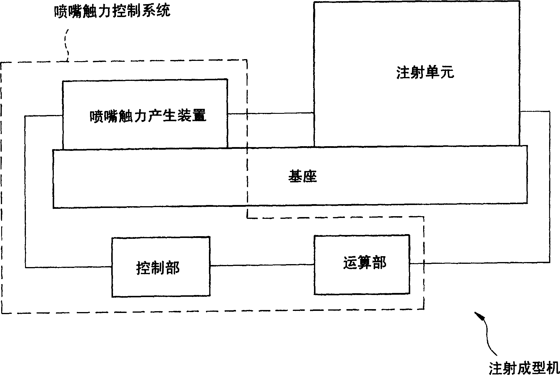
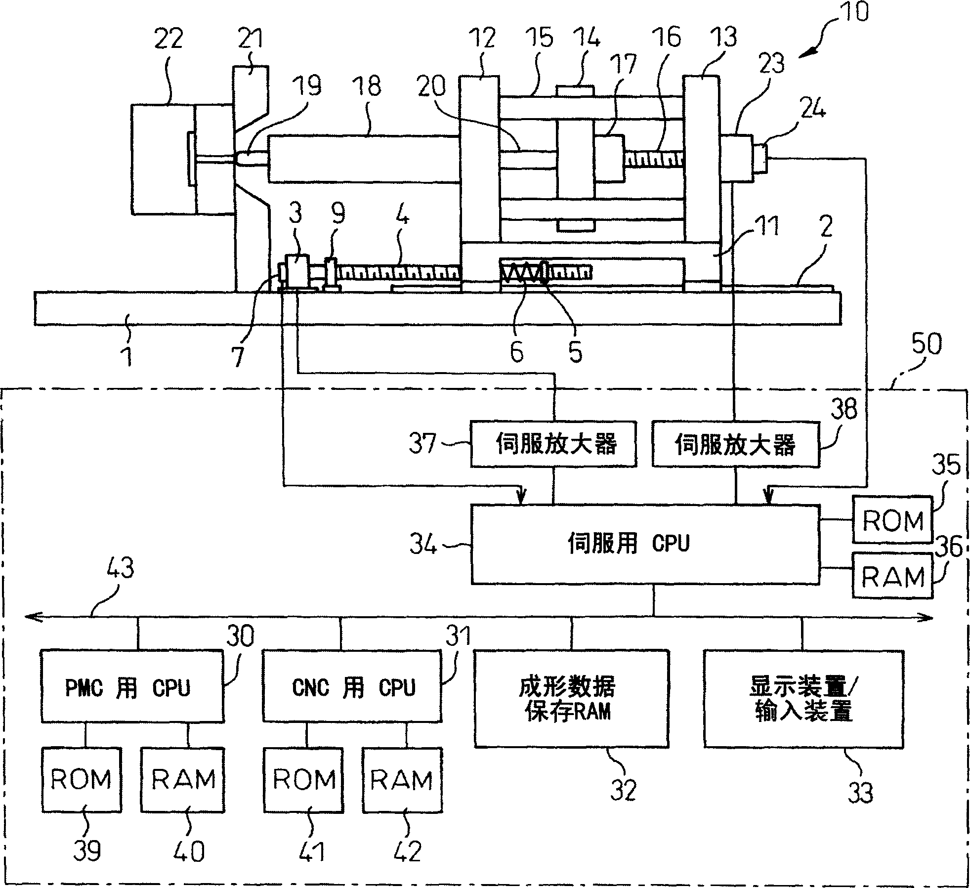
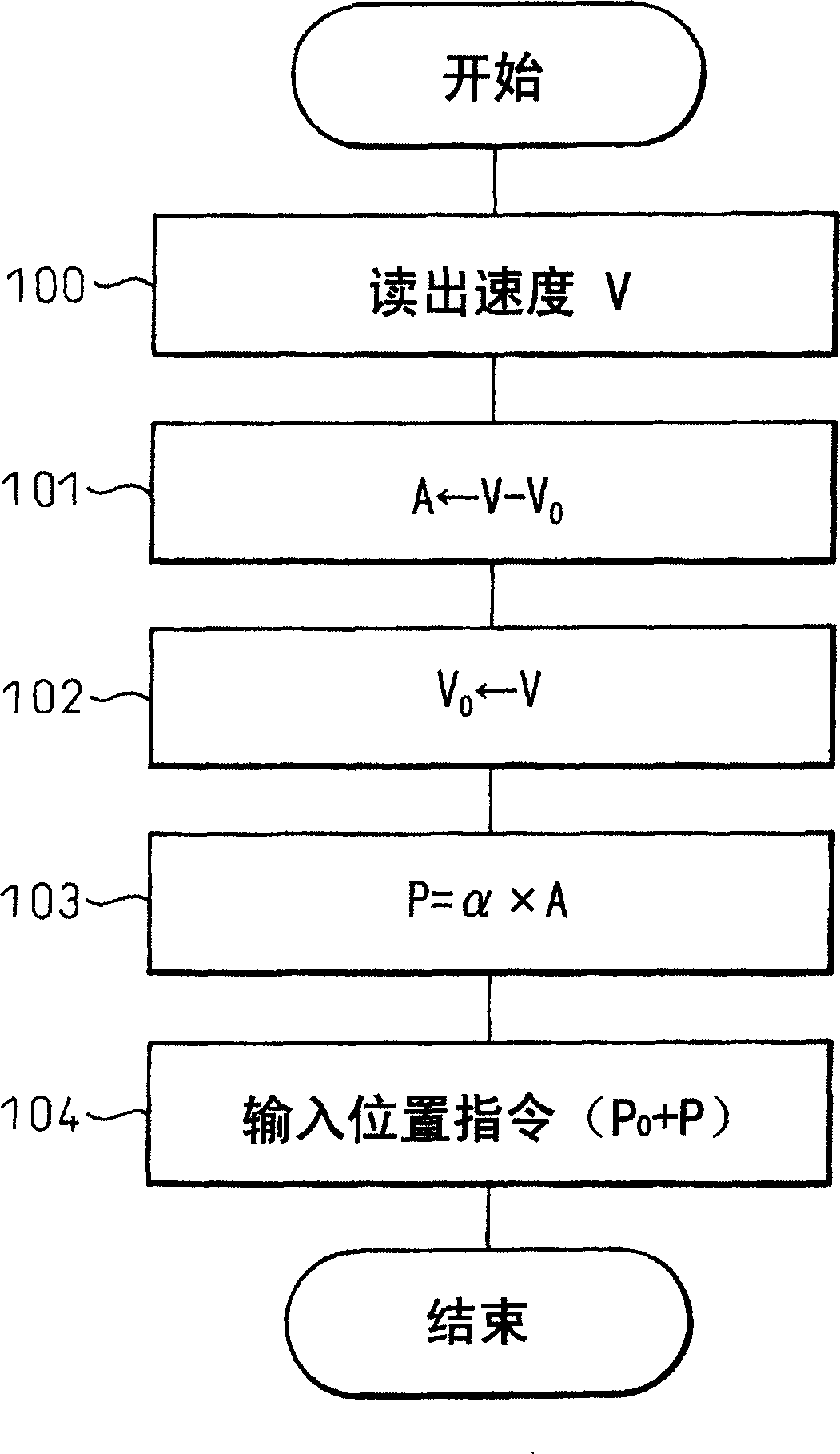
[0028] The present invention is to remove the influence of the inertial force of the movable part during the injection acceleration and deceleration during the injection, to always keep the nozzle contact force constant, to obtain the acceleration during injection (injection spiral acceleration), and to obtain the nozzle contact force based on this acceleration. The influence that controls the force generated by the nozzle contact force generating device. During injection, the molten resin is injected by movable parts such as injection screw or push plate, and it accelerates and decelerates. The inertial force is obtained by multiplying the acceleration during acceleration and deceleration by the mass of the movable part to be accelerated and decelerated. Therefore, the force that influences the nozzle contact force can be obtained by multiplying the acceleration during injection with a predetermined constant. In the present invention, the inertial force accompanying the accel...


PUM


Abstract

The invention relates to a kind of controlling system that can maintain the touching force of spraying spout with simple structure. The electric machine impels the injection unit to move forward with spring and touches the spout and the model. The pressed spring supplies certain force. During process of injecting and maintaining pressure, drive the screw and use location / speed checker, which is set in the servo injecting colophony electric machine, to check injection speed after every certain period. Get the acceleration according to the injection speed, and then get the inertia force caused by moving of injecting screw and push pedal. With the same amount of force as the inertia force to change the mechanic machine rotating position and to control the force pressed on the spring so as to maintain a certain spout touching force. The certain touching force of the spout can prevent colophony from leaking. It won't generate too heavy touching force also.

Description

technical field [0001] The invention relates to an injection molding machine, in particular to a nozzle contact force control system of the injection molding machine. Background technique [0002] The nozzle contact mechanism that moves the injection unit as a whole and contacts and presses the mold drives the injection unit mounted on the base that can move forward and backward through the nozzle contact force generating device, so that the nozzle of the injection unit contacts the mold. As a nozzle contact force generating device, a device using a hydraulic cylinder or a spring force that uses electric power to expand and contract is known to press and hold the nozzle and the mold (refer to Japanese Patent Publication No. 6-17038). [0003] Furthermore, there is also known a nozzle contact mechanism that presses the nozzle against the mold with a certain pressure using oil pressure. In this way, the existing nozzle contact force control is generally to keep the output of ...

Claims


Application Information

Patent Timeline
Patent Type & Authority Applications(China)
IPC IPC(8): B29C45/20B29C45/17B29C45/76
CPCB29C2945/76006B29C2945/76511B29C2945/76381B29C2945/76933B29C2945/76113B29C2945/7611B29C2945/76785B29C2945/76595B29C45/76B29C2945/76187B29C2945/76568B29C2945/76083B29C2945/76939B29C2945/76505B29C2945/76498B29C2945/76307B29C45/1777B29C2945/76695B29C2945/76525
Inventor 长谷元弘川崎达也桥本展明
Owner FANUC LTD
Learn More