
Electromagnetic plunge pump

A technology of electromagnetic plunger and plug pumps, which is applied in the direction of pumps, liquid variable displacement machines, engine components, etc., and can solve problems such as low oil supply pressure

Inactive Publication Date: 2005-03-02
汪峰
View PDF0 Cites 1 Cited by
  • Summary
  • Abstract
  • Description
  • Claims
  • Application Information

AI Technical Summary

Problems solved by technology

[0003] In view of the defect of low oil supply pressure of the current electromagnetic plunger pump, the purpose of the invention is to provide an electromagnetic plunger pump with an oil supply pressure above 2.5 bar, low cost, low power consumption and small volume

Method used


Image

  • Electromagnetic plunge pump
  • Electromagnetic plunge pump
  • Electromagnetic plunge pump

Examples


Embodiment Construction

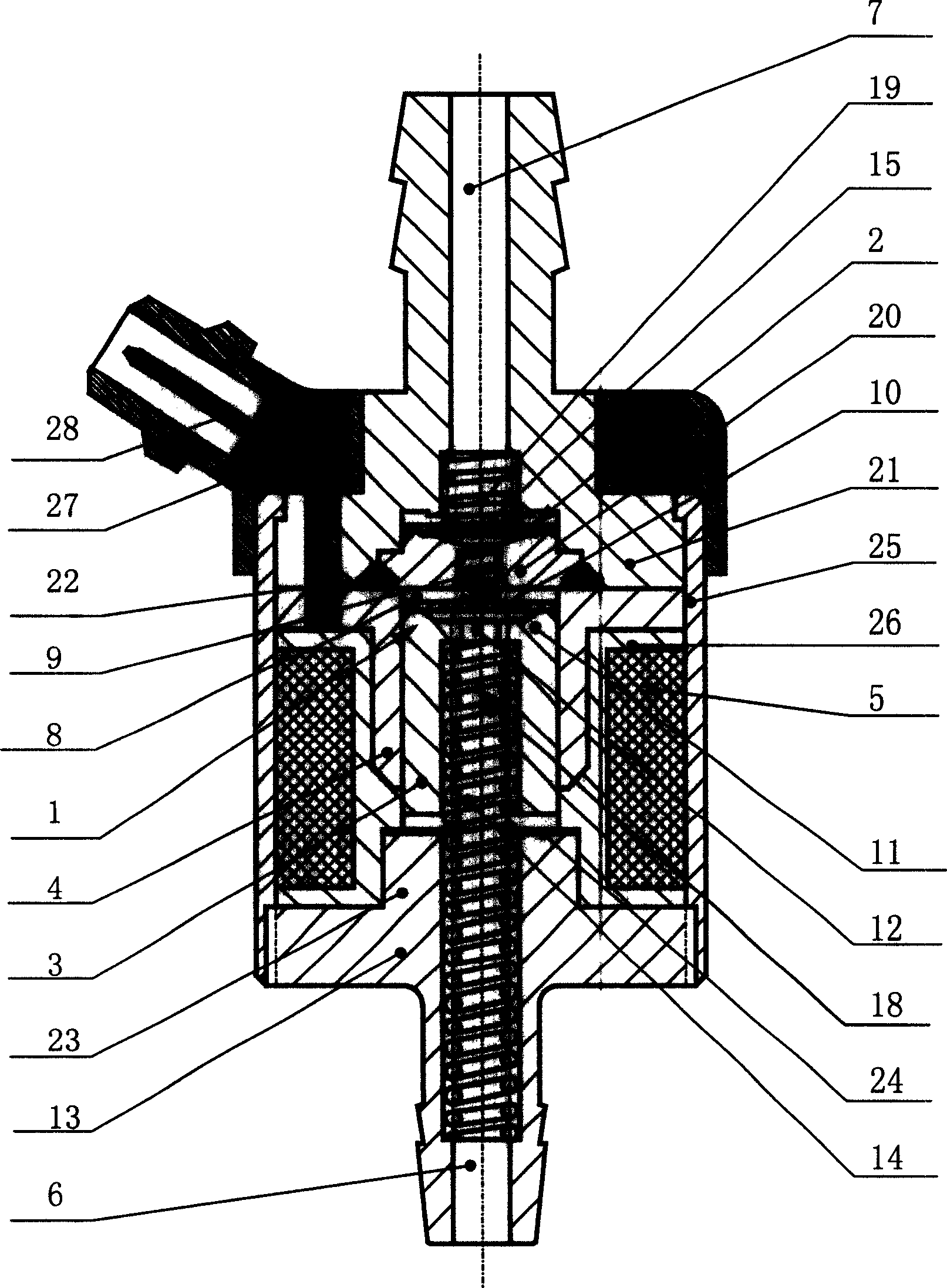
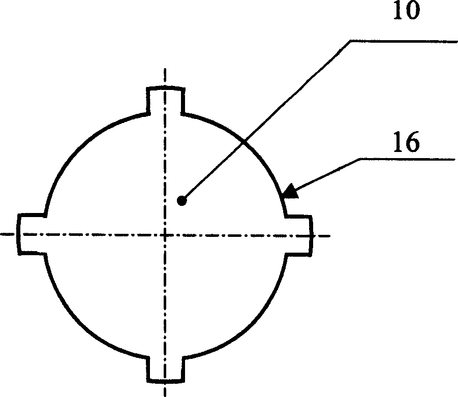
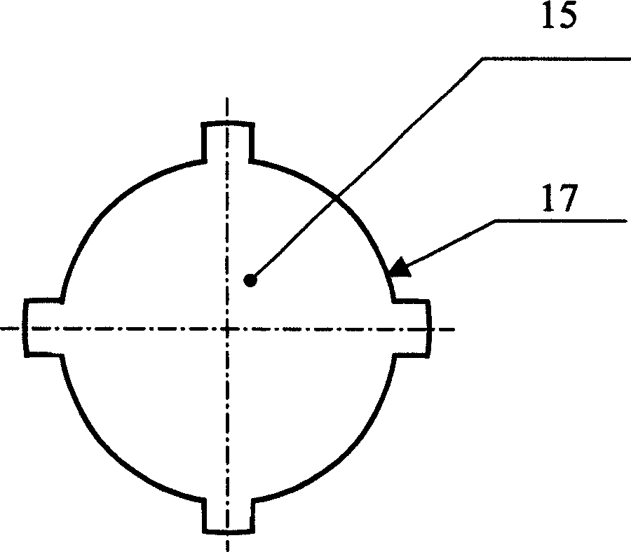
[0009] Below in conjunction with accompanying drawing, the present invention will be further described (with reference to figure 1 ). The principle is as mentioned above, the plunger 3 and the plunger sleeve 4 belong to a dynamic sealing fit, and the coil 5 drives the plunger 3 to move in the plunger sleeve 4 . There is an oil inlet hole 12 and a cylindrical spring chamber 18 inside the plunger 3 , so that the oil inlet 6 communicates with the oil inlet valve 1 . Between the plunger 4 and the lower end cover 13, a plunger return spring 14 is arranged along the axis line of the plunger 3, and about 1 / 3 of the length of the plunger return spring 14 is installed in the spring chamber 18, and the top of the spring and the spring chamber top surface contact. The valve seat 11 of the oil inlet valve is designed on the top of the plunger, which is beneficial to further reduce the volume of the compression chamber 8 . The shape of the oil inlet valve spool 10 is as figure 2 As sh...


PUM


Abstract

The invention relates to a electromagnetic tube-plug pump, using for pressure oil supplying in the oil-spraying system of compressor. It mainly includes oil-entering salves, oil-out salve, shaft-plug, coil and so on. The oil-entering salve includes an oil-entering salve spring, the oil-entering salve pith, and an oil-entering salve stand. The oil-entering salves stand is connected with plug, and communicated with oil-entering salve stand. The oil-entering salve stand is connected with plug, and communicated with oil-entering entrance by oil-entering holes inside the shaft-plug. There is a reduced spring between the shaft-plug and the lid bellow, along with the axis of shaft-plug, the shape of the entrance and exit of oil salve pith is disc, outside are oil-entering groove and oil-out groove. The benefit result of this invention is: because there is no reduce spring in the compressor cavity, it can reduce the dangerous capacity in the cavity, enhance the self-absorbing capacity and reduce air-hindernig phenomenon. That makes sure a higher oil-supporting pressure and especially apply for the electric-controlling spraying system of the motor engine. Certainly it also can apply for the other areas.

Description

technical field [0001] The invention relates to an electromagnetic plunger pump used for pressure fuel supply in an electronically controlled fuel injection system of a gasoline engine. Background technique [0002] The gasoline pump used in the electronically controlled fuel injection system of a gasoline engine is required to be able to provide fuel with a pressure above 2.5bar stably. At present, a rotor pump driven by a DC motor is generally used in the market. The disadvantages are that it is more expensive, and the power consumption and The installation volume is large, and these characteristics make this type of oil pump not suitable for application on small gasoline engines such as motorcycle engines. At present, the electromagnetic plunger pump used in carburetor gasoline engine has low price and electric power, but the fuel supply pressure is low, so it is not suitable for EFI system, and can only be used to supply low-pressure fuel to c...

Claims


Application Information

Patent Timeline
Patent Type & Authority Applications(China)
IPC IPC(8): F02M51/04F04B17/04
Inventor 汪峰
Owner 汪峰
Learn More