
Purifier for harmful gases

A technology for harmful gases and purification devices, applied in gas treatment, incinerators, chemical instruments and methods, etc., can solve problems such as hindering the uniform mixing of harmful gases, reducing the decomposition rate of harmful gases, and reducing combustion temperature, and achieve safe and stable purification treatment. , The effect of suppressing the accumulation of powder and preventing thermal diffusion

Inactive Publication Date: 2005-02-23
JAPAN PIONICS
View PDF0 Cites 5 Cited by
  • Summary
  • Abstract
  • Description
  • Claims
  • Application Information

AI Technical Summary

Problems solved by technology

As a result, it hinders the uniform mixing of harmful gases and combustion gas, air, oxygen, etc., hinders complete combustion, not only reduces the combustion temperature, reduces the decomposition rate of harmful gases that are treated, but also increases the accumulation of powders. In many places, there is a danger of fire

Method used


Image

  • Purifier for harmful gases
  • Purifier for harmful gases
  • Purifier for harmful gases

Examples


no. 1 Embodiment

[0033] (manufacturing of purification equipment)

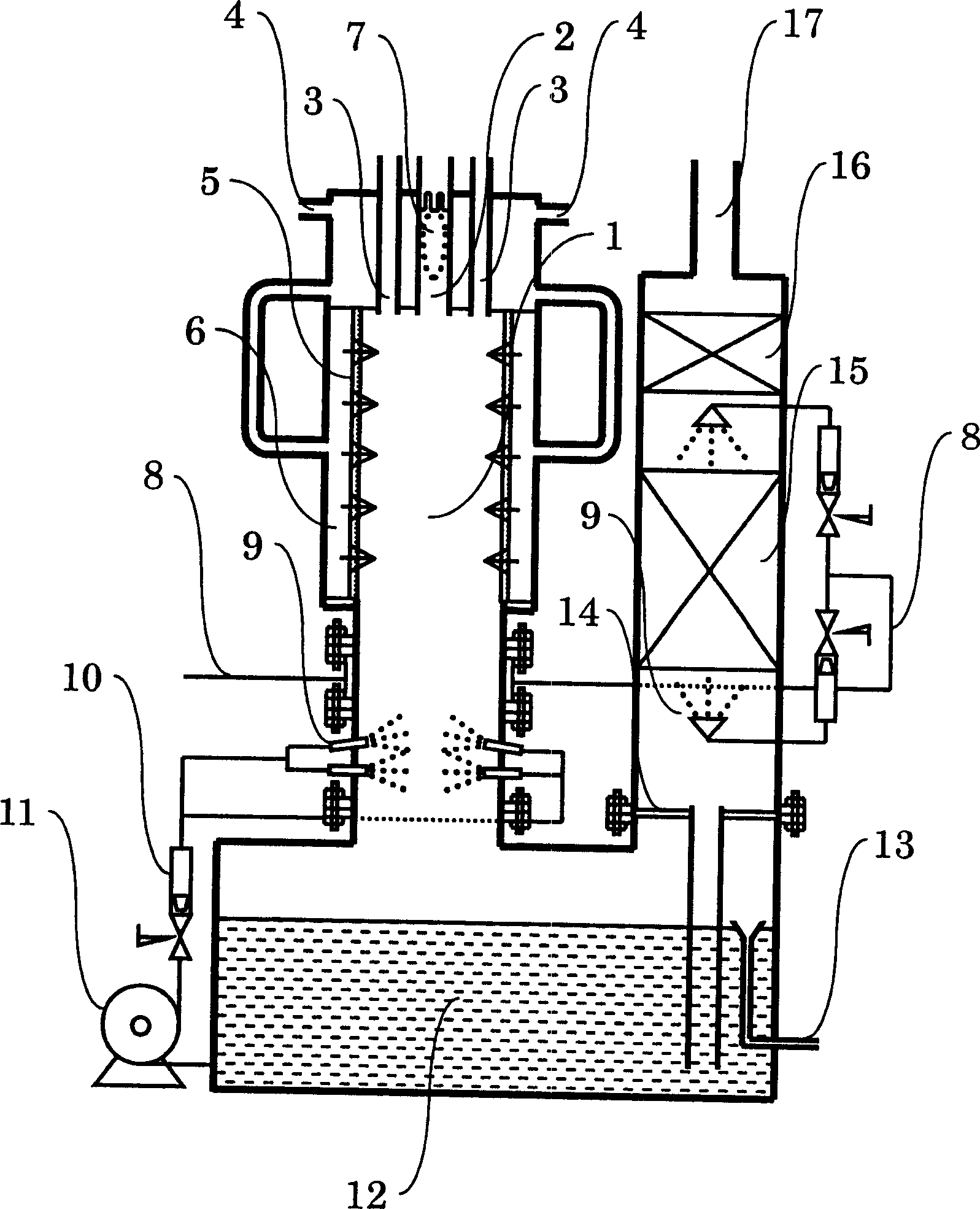
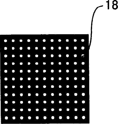
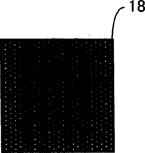
[0034] make figure 1 As shown, the outer wall is made of stainless steel (SUS316) and has a height of 2000mm. A cylinder made of aluminum having fine pores as shown in FIG. 2( b ) was used as the heat insulating wall on the side of the thermal decomposition chamber. The heat insulating wall has a diameter of 300 mm, a length of 600 mm, and a thickness of 25 mm, and has micropores corresponding to a diameter in the range of 10 to 100 μm. In addition, a stainless steel cylinder with a diameter of 480 mm and a thickness of 3 mm was used as the outer wall on the outer side. In addition, the inner diameter of the nozzle leading the combustion exhaust into the thermal decomposition chamber is 32 mm, the inner diameter of the nozzle leading the harmful gas into the thermal decomposition chamber is 44 mm, and the length is 200 mm.

[0035] At the bottom of the purification device, set a water tank with a longitudinal dimension of 1...


PUM

PropertyMeasurementUnit
diameteraaaaaaaaaa
lengthaaaaaaaaaa
thicknessaaaaaaaaaa

Abstract

The invention relates to a harmful gas purifier, and provides a cleaning facility capable of stably removing a harmful gas discharged from a semiconductor manufacturing process in safety for a long time by inhibiting the lowering of a decomposition ratio of a treated harmful gas and the accumulation of powdered matter on a wall face of a decomposition chamber without using a large-scaled or complicated constitution. In this cleaning facility for removing the harmful gas discharged from the semiconductor manufacturing process by thermally decomposing the harmful gas by the combustion waste gas or flame obtained by burning the fuel, a side face of the thermal decomposition chamber is a wall having air permeability and heating insulating property, and the oxygen-containing gas is introduced into the thermal decomposition chamber through the wall.

Description

technical field [0001] The present invention relates to a purification device for removing harmful gas having harmful components discharged from semiconductor manufacturing steps. More specifically, the present invention relates to a purifying device for separating harmful gas having harmful components discharged from a semiconductor manufacturing step from combustion exhaust gas obtained by burning fuel or It is thermally decomposed by flame contact, thereby turning it into a harmless substance or a substance that can be easily detoxified. Background technique [0002] With the development of the semiconductor industry in recent years, various gases are used in semiconductor manufacturing steps. However, these gases are mostly harmful substances to the human body and the environment, and must be purified before being discharged outside the factory. Combustion of these gases, thus, the combustion type purification method of decomposition treatment is a convenient method th...

Claims


Application Information

Patent Timeline
Patent Type & Authority Applications(China)
IPC IPC(8): B01D53/34B01D53/81B01D53/82F23G5/027F23G7/06
CPCB01D53/005B01D2251/102B01D2258/0216F23G5/027F23G7/06
Inventor 岛田孝小礒保彦村永直树笠谷尚史池田友久
Owner JAPAN PIONICS
Learn More