
Suspending hydraulic pillars

A hydraulic prop and suspension technology, which is applied in the direction of props/brackets, mining equipment, earth drilling, etc., can solve the problems of movement wear, waste, and waste of a large amount of wood

Inactive Publication Date: 2005-02-23
CHINA UNIV OF MINING & TECH
View PDF0 Cites 8 Cited by
  • Summary
  • Abstract
  • Description
  • Claims
  • Application Information

AI Technical Summary

Problems solved by technology

The support equipment used in my country's mines includes wooden props, single metal friction props, single hydraulic props and double telescopic suspension props, etc. Because wooden props waste a lot of wood, and the supporting force is easy to change, there is no constant increase in resistance and drop distance. The stability is poor, so it is rarely used; although the support force of the single metal friction prop is stronger than that of wood, but because of the small and uneven initial support force, the constant increase in resistance and drop distance cannot be guaranteed; The new generation of products developed after the pillars has been popularized and applied for more than 20 years. There are two types of single hydraulic props: internal injection type and external injection type. The body hydraulic prop is of the outer column type, and there is a three-purpose valve on it. Through the three-purpose valve, the pressure liquid supplied by the emulsion station preset on the working face is injected into the prop oil cylinder for initial support. When the top plate is pressed and unloaded, it is passed through three Use the valve to release the emulsion, lower the pillar, and use the pressure fluid of the emulsion station for initial support when the work is repeated, and cycle in turn
The use of this single hydraulic prop has brought great convenience to the mining face, but there are the following problems: 1) because the three-purpose valve seat that is set on this kind of hydraulic prop is welded on the stressed active post, It affects the strength of the live column; 2) The live column and the cylinder column are prone to wear when moving between the cylinder and the oil cylinder, resulting in the live column being stuck; 3) Since the inner surface of the oil cylinder is the high-pressure sealing surface of the single hydraulic prop, its production cost 4) The quality of the underground water in coal mines is poor, and the quality of the prepared emulsion is generally not guaranteed, resulting in serious corrosion of the oil tank, and it is easy to make the pillars scrapped. The scrapped amount of pillars reaches 300,000 every year, causing great waste

Method used


Image

  • Suspending hydraulic pillars
  • Suspending hydraulic pillars

Examples


Embodiment Construction

[0009] An embodiment of the present invention will be further described below in conjunction with accompanying drawing:

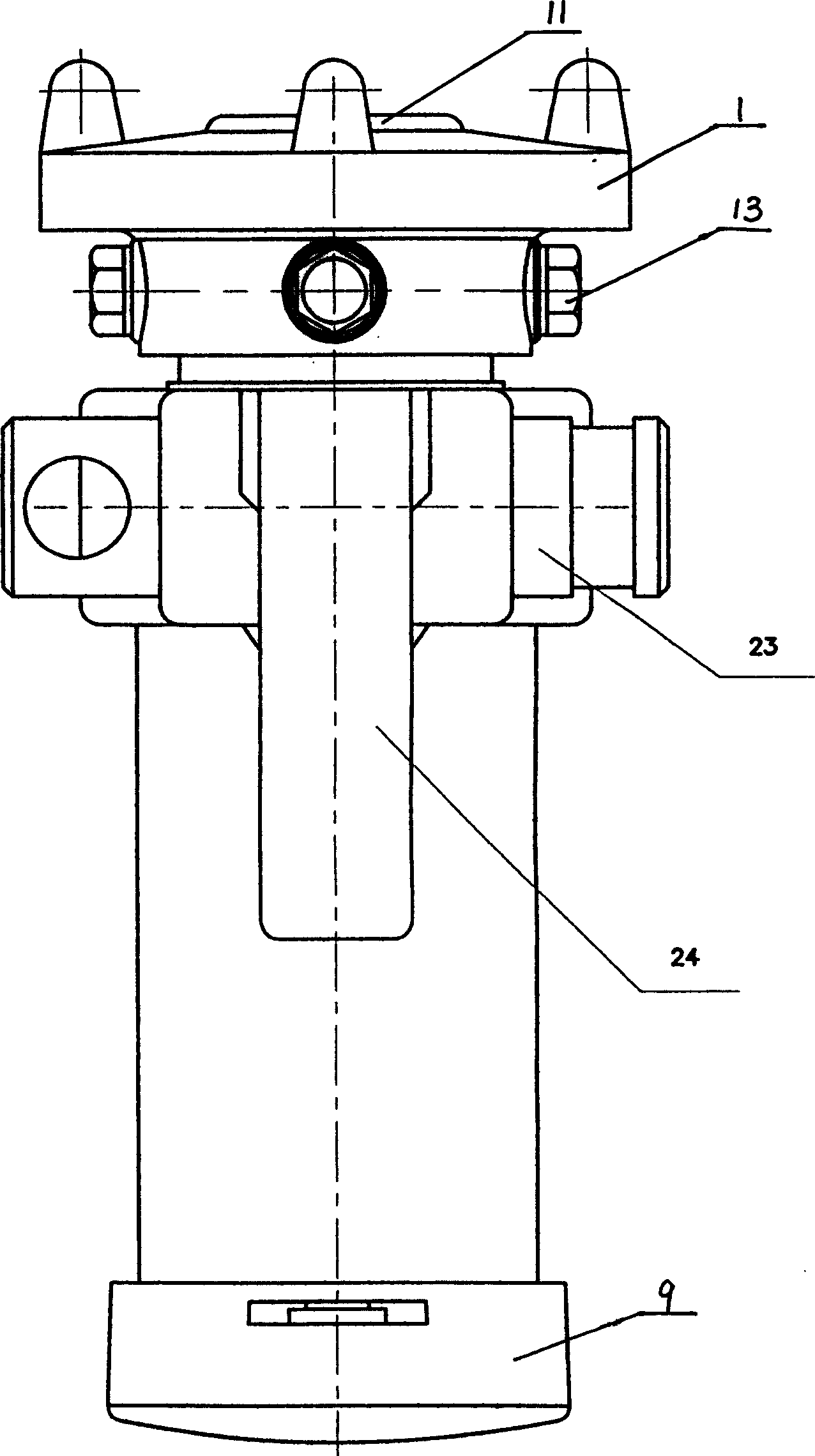
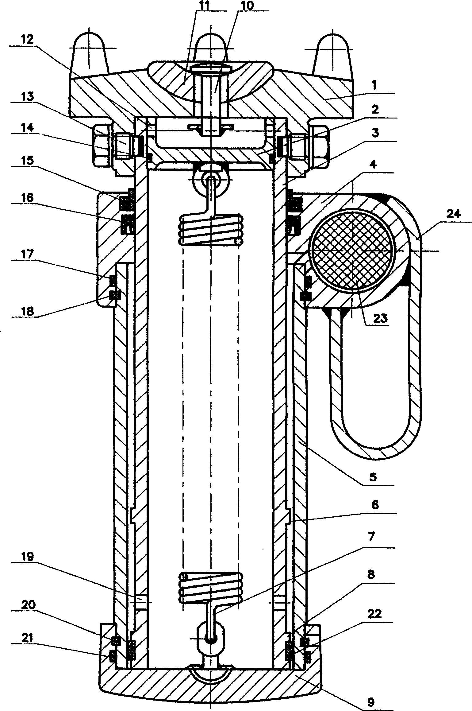
[0010] The suspended hydraulic prop of the present invention mainly consists of a top cover 1, a sealing cover 2, a live column 3, a valve body 4, an oil cylinder 5, a return spring 7, a three-purpose valve 23 and a base 9. The sealing cover 2 is arranged on the top of the inner diameter of the live column 3, and the inner diameter of the upper end of the live column 3 is provided with a shoulder which prevents the sealing cover 2 from falling. Contact the top cover when the pillar supports, and leave the top cover when returning to the pillar. The hook at the upper end of the return spring 7 is hung on the hanging ring in the middle of the bottom of the sealing cover 2; the top cover 1 fits on the outer cylindrical surface of the live post 3, and the top cover 1 and the live post 3 are fastened together with pin head screws 13 , the head of pin head screw...


PUM


Abstract

The present invention relates to a suspended hydraulic prop stanchion, most suitable for support of mine underpit working face. It is mainly formed from oil cylinder, movable prop, sealing cover, reset spring, top cover, bottom seat, pin joint screw and three-way valve. Said invention also provides the connection method of all the above-mentioned components and their actions. Said invented hydraulic prop stanchion is compact and reasonable in structure, good in stability, high in strength, large in load-bearing capacity, light in weight and good in safety, so that it has extensive practicality.

Description

1. Technical field: [0001] The invention and a suspension hydraulic prop are especially suitable for the support of mining working faces in underground mines and also suitable for other occasions requiring support. 2. Background technology: [0002] The support of the underground mining face is one of the essential equipment in the mine. The support equipment used in my country's mines includes wooden props, single metal friction props, single hydraulic props and double telescopic suspension props, etc. Because wooden props waste a lot of wood, and the supporting force is easy to change, there is no constant increase in resistance and drop distance. The stability is poor, so it is rarely used; although the support force of the single metal friction prop is stronger than that of wood, but because of the small and uneven initial support force, the constant increase in resistance and drop distance cannot be guaranteed; The new generation of products developed after the pillars h...

Claims


Application Information

Patent Timeline
IPC IPC(8): E21D15/45
Inventor 李炳文朱真才王启广赵继云陈世其王建武陈为民周玉萍王敬
Owner CHINA UNIV OF MINING & TECH
Learn More