
Exchange medium convertor and passive optical network using same

An optical network system and converter technology, applied in data switching networks, wavelength division multiplexing systems, optical multiplexing systems, etc., can solve problems such as cost and function problems

Inactive Publication Date: 2005-02-16
崔埈国
View PDF1 Cites 5 Cited by
  • Summary
  • Abstract
  • Description
  • Claims
  • Application Information

AI Technical Summary

Problems solved by technology

[0012] The ring network configuration mentioned above has redundancy for all nodes, but can be cost and functionally problematic

Method used


Image

  • Exchange medium convertor and passive optical network using same
  • Exchange medium convertor and passive optical network using same
  • Exchange medium convertor and passive optical network using same

Examples


Embodiment Construction

[0027] Now, preferred embodiments of the present invention will be described in detail with reference to the accompanying drawings. In the following description of the present invention, a detailed description of known functions and specific structures will be omitted here when it would obscure the gist of the present invention.

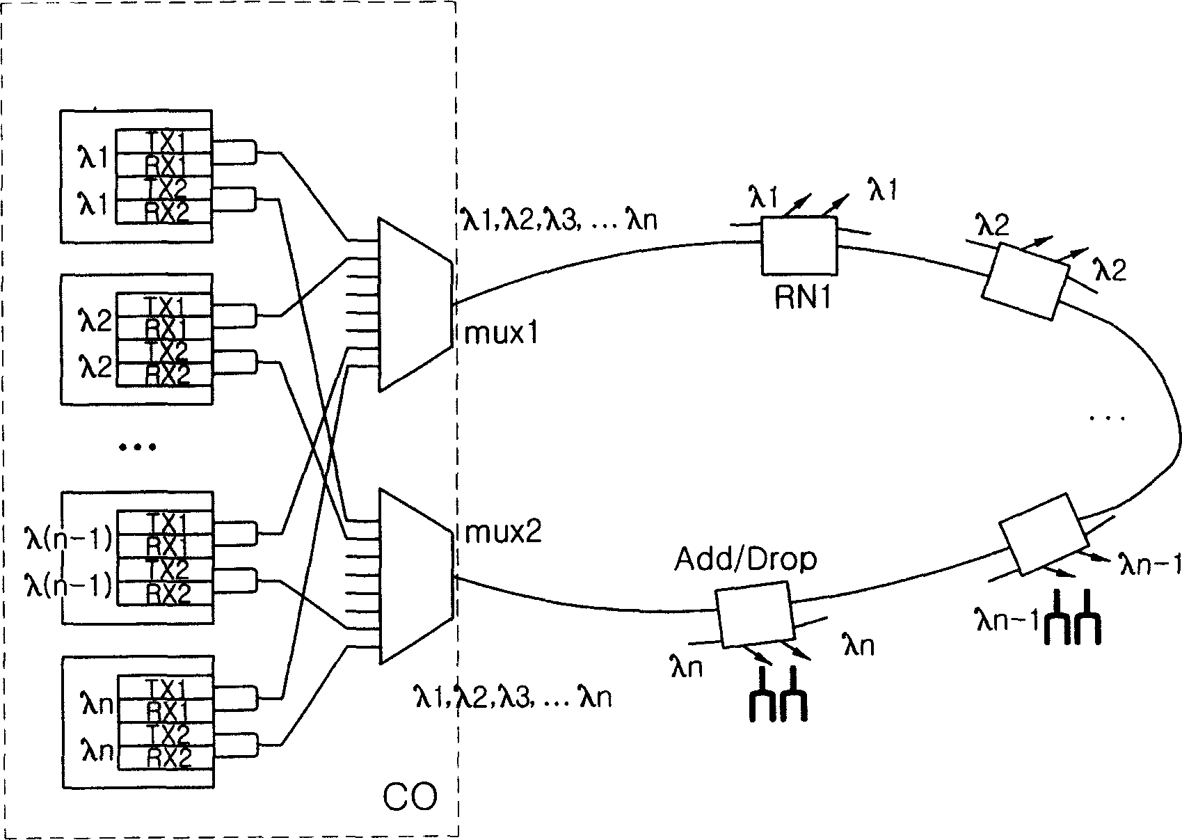
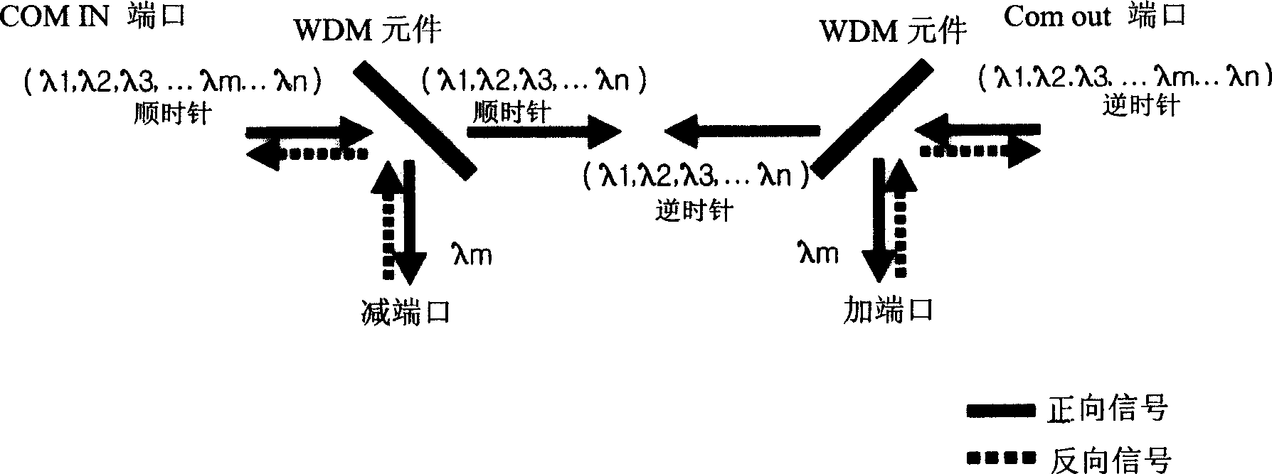
[0028] figure 2 It is a schematic diagram illustrating the structure of a ring WDM PON system using the same wavelength for forward and reverse channels according to an embodiment of the present invention. image 3 is an example such as figure 2 A schematic diagram of the structure of the 4-port adder / subtractor 120 shown. Figure 4 is an example such as figure 2 A schematic diagram of the detailed structure of the medium of exchange converter 130 is shown for redundancy purposes.

[0029] refer to figure 2 , the ring WDM PON system according to the illustrated embodiment of the present invention includes a central office (CO), and a bidirec...


PUM


Abstract

Disclosed is a ring type wavelength division multiplexing (WDM) passive optical network (PON) system using the same wavelength for forward and backward channels while inexpensively implementing a redundancy function, and a switching media converter usable in the ring type WDM PON system. The WDM PON system provided a redundancy function to each node, so that the central office of the system can have a simplified architecture. Accordingly, there is an advantage in that the construction costs of the central office can be reduced. And, the network construction costs can be minimized because it is possible to provide a desired redundancy to a part of the nodes, taking into consideration the significance of each node.

Description

technical field [0001] The present invention relates to a wavelength division multiplexing (WDM) passive optical network (PON) system, in particular to a ring-shaped WDM PON system that uses the same wavelength for forward and reverse channels and can economically realize redundant functions at the same time, and for Swap medium converter for ring WDM PON systems. Background technique [0002] It is well known that a wavelength division multiplexing (WDM) system allocates different wavelengths to each user through a central office (CO), so that the central office can send data to the user end synchronously. Individual users can also send data using different assigned wavelengths. The beauty of this system is that it can provide a large amount of information to each user while maintaining a high level of security and easy performance upgrades. [0003] Also, PON is known to have a structure based on an optical network. In the PON, an Optical Line Terminal (OLT) is connecte...

Claims


Application Information

Patent Timeline
Patent Type & Authority Applications(China)
IPC IPC(8): H04B10/03H04B10/032H04B10/035H04B10/077H04B10/27H04B10/272H04B10/275H04B10/29H04J3/16H04J14/00H04J14/02H04L12/42H04L12/437H04L12/44H04Q11/00
CPCH04J14/029H04J14/0294H04J14/0216H04J14/0287H04J14/0283H04J14/0297H04J14/0213H04Q11/0067H04J14/0227H04Q2011/0081H04J14/0246H04J14/0206H04J14/0282H04Q2011/0092H04L12/42
Inventor 崔埈国李素瑛姜昇旼
Owner 崔埈国
Learn More