
Disc and hub assembly for electromagnetic clutch in a compressor

An electromagnetic clutch and assembly technology, applied in the direction of magnetic drive clutches, non-mechanical drive clutches, clutches, etc., can solve the problems of damage to the friction surface of the disc 20 and the pulley, problems with the durability of the leaf spring 30, and reduced power transmission efficiency. , to improve power transmission efficiency, improve noise reduction effect, reduce noise and impact

Inactive Publication Date: 2005-02-02
HANON SYST
View PDF0 Cites 4 Cited by
  • Summary
  • Abstract
  • Description
  • Claims
  • Application Information

AI Technical Summary

Problems solved by technology

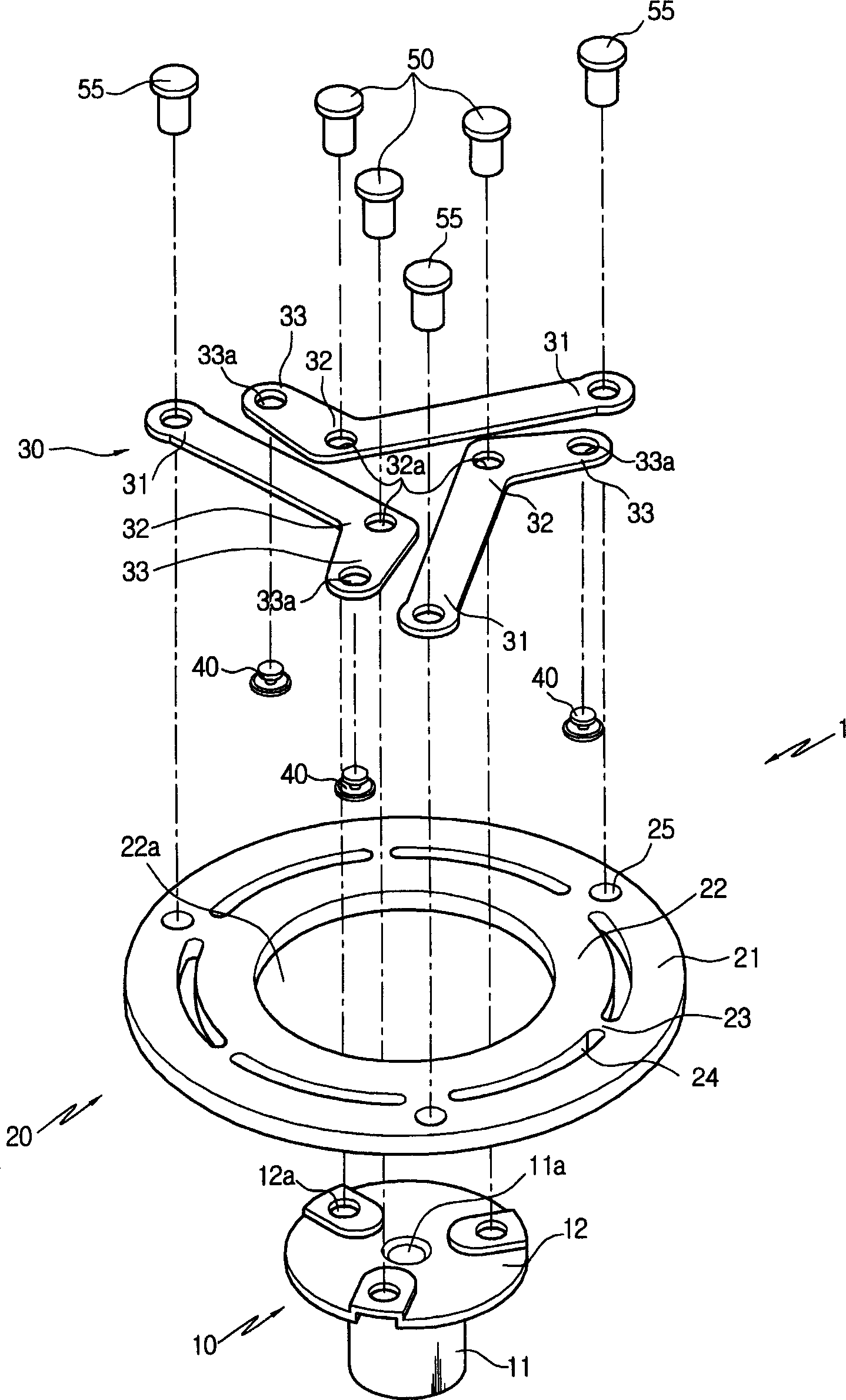
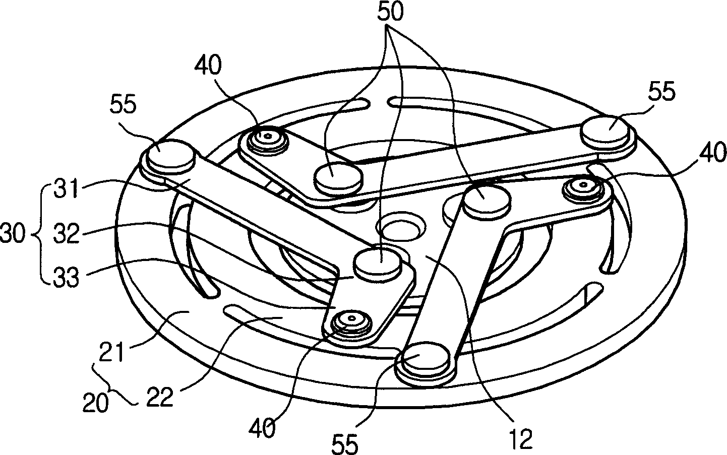
[0016] However, the conventional disk and hub assembly 1 has a problem in product applicability due to the large noise generated in the structure when the electromagnetic clutch is engaged / disengaged.
[0017] That is, if power is applied to the electromagnetic coil, the disk 20 is attracted to the friction surface of the pulley. At this time, due to the impact between the disk 20 and the pulley, metal hitting sound is generated and noise is formed, and the noise is transmitted to the interior of the vehicle. In the case of the vehicle, there is a problem of causing discomfort to the driver, etc.
[0018] In addition, the arcuate cutout 24 formed on the disc 20 is exposed to the outside, so dust and foreign matter may enter the friction surface side of the pulley through the cutout 24, causing the friction force between the pulley and the disc 20 to decrease, The power transmission efficiency is lowered, and there is a problem that the friction surfaces of the disc 20 and the pulley are damaged
[0019] And, the durability of the leaf spring 30 also has problems

Method used


Image

  • Disc and hub assembly for electromagnetic clutch in a compressor
  • Disc and hub assembly for electromagnetic clutch in a compressor
  • Disc and hub assembly for electromagnetic clutch in a compressor

Examples


Embodiment Construction

[0034] Hereinafter, a preferred embodiment of the present invention will be described in detail with reference to the drawings.

[0035] In addition, description of the same configuration and function as conventional ones is omitted.

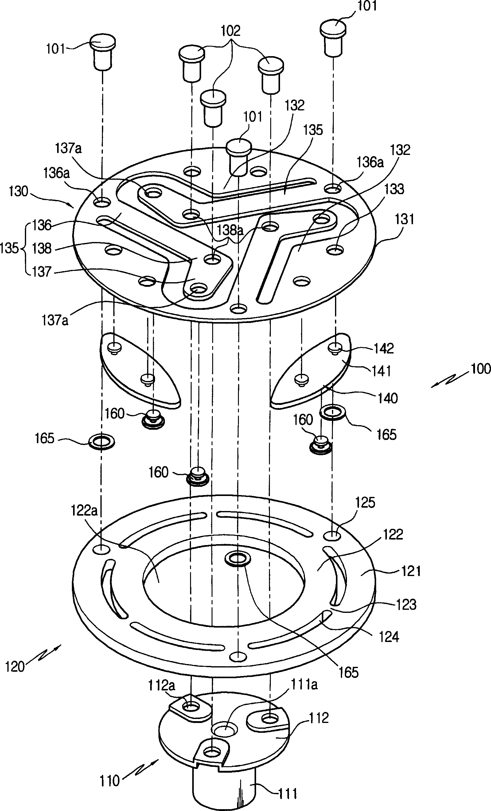
[0036] image 3 It is an exploded perspective view showing a disc and hub assembly of the first embodiment of the present invention, Figure 4 It is an assembly perspective view showing the disc and hub assembly of the first embodiment of the present invention.

[0037] As shown in the figure, the disc and hub assembly 100 of the present invention includes: a hub 110 , a disc 120 , a leaf spring 130 and a buffer unit 140 .

[0038] First, the hub 110 is composed of a hub main body 111 having an engagement hole 111a for spline engagement with a drive shaft (not shown) of a compressor (not shown), and a hub body 111 formed on the hub main body 111. The flange 112 on the side outer peripheral surface constitutes. A plurality of rivet engaging h...


PUM


Abstract

The present invention relates to a disc and hub assembly for an electromagnetic clutch of a compressor. The assembly comprises: a disc adapted to be attracted to or separated from a friction surface of a pulley under the action of an electromagnetic coil; a hub coupled to a driving shaft of the compressor, the hub penetrating the disc and having a flange formed on its outer peripheral surface; a plate spring which includes a plate portion coupled to the top surface of the disc, a number of leaf spring portions obliquely extending inwardly from the plate portion to be coupled to the flange of the hub and having ends which are bent toward the disc, and dampers coupled to the ends of the leaf spring portions; and shock-absorbing means interposed between the disc and the plate portion to reduce noise and impact during on / off of the clutch.

Description

technical field [0001] The present invention relates to a disc and hub assembly for an electromagnetic clutch of a compressor, in particular to an assembly between the disc and a leaf spring in order to reduce noise and impact when the clutch is engaged (ON) / disengaged (OFF). The shock absorber prevents damage such as detachment or cracking due to the centrifugal force of the shock absorber, improves durability, and further improves the noise reduction effect of the electromagnetic clutch disc and hub assembly of the compressor. Background technique [0002] The compressor, which is a component of the air-conditioning system of the car, is a device that selectively receives the power of the engine transmitted through the pulley by the clutching action of the electromagnetic clutch, compresses the refrigerant supplied from the evaporator, and sends it to the condenser. [0003] The electromagnetic clutch that transmits the power of the engine to the compressor includes: a rot...

Claims


Application Information

Patent Timeline
Patent Type & Authority Applications(China)
IPC IPC(8): F16D27/112
CPCF16D2027/007F16D27/112
Inventor 申壮淳孙殷基
Owner HANON SYST
Learn More