Handle and latch for a removable dirt separation system

A detachable and handle technology is applied in the handle and latching field of detachable dirt separation system, which can solve the problem that the dirt cup cannot be moved with the handle, etc.

Inactive Publication Date: 2005-01-26
HOOVER LIMITED
View PDF0 Cites 6 Cited by
  • Summary
  • Abstract
  • Description
  • Claims
  • Application Information

AI Technical Summary

Problems solved by technology

A disadvantage of these systems is that the operator cannot use the lifting handle to manipulate the dirt cup when the cover is removed from the dirt cup

Method used


Image

  • Handle and latch for a removable dirt separation system
  • Handle and latch for a removable dirt separation system
  • Handle and latch for a removable dirt separation system

Examples


Embodiment Construction

[0032] While the present invention is susceptible to various modifications and alternative forms, specific embodiments thereof have been shown by way of example in the drawings and described in detail herein. It should be understood, however, that there is no intention to limit the invention to the particular forms described, but on the contrary, the invention is intended to cover all modifications, equivalents and modifications falling within the spirit and scope of the invention as defined by the appended claims. and replace.

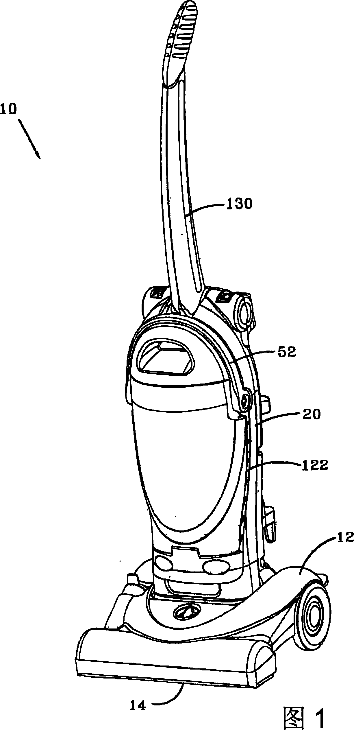
[0033] Referring now to FIG. 1 , there is shown an upright vacuum cleaner 10 incorporating features of the present invention. The vacuum cleaner 10 includes a vacuum cleaner base 12 and a vacuum cleaner upper housing 20 pivotally connected to the base 12 . The base 12 is adapted to engage a carpeted floor. The base 12 includes a nozzle opening 14 formed therebelow for suctioning dirt particles from a carpeted floor. Additionally, an agitator 154 (s...


PUM


Abstract

An upright vacuum cleaner is disclosed. The upright vacuum cleaner includes a carpet engaging nozzle base and an upper housing pivotally attached to the nozzle base. The upright vacuum cleaner further includes a removable bucket releasably secured to the upper housing and a bucket handle rotatably attached to the bucket and movable between a first position and a second position. The upright vacuum cleaner yet further includes a latch adapted to secure the bucket to the upper housing when the handle is in the first position and release the bucket from the upper portion when the handle is in a second position. The bucket may be removed from the upper housing when the latch is released from the upper housing. The bucket is re-secured to the upper housing by returning the bucket handle to the first position. A method of operating a upright vacuum cleaner is also disclosed.

Description

technical field [0001] The present invention relates to vacuum cleaners. More specifically, the present invention relates to handles and latches for removable dirt separation systems for vacuum cleaners. Furthermore, the invention relates to a handle and a latch for a detachable dirt separation system for use in a bagless vacuum cleaner. Background technique [0002] Upright vacuum cleaners are well known in the art. Typically, these vacuum cleaners include an upper housing pivotally mounted to the bottom of the vacuum cleaner. The bottom is formed with a nozzle opening defined therebelow and may include an agitator mounted therein for loosening dirt and debris from the floor. Motors and fans can be mounted to the bottom or housing to generate suction at the mouth of the nozzle. Suction from the mouth of the nozzle picks up loose dirt and debris and creates a dirt-laden airflow that is transported to the housing of the vacuum cleaner. [0003] In conventional vacuum cle...

Claims


Application Information

Patent Timeline
Patent Type & Authority Applications(China)
IPC IPC(8): A47L5/28A47L5/32A47L9/10A47L9/12A47L9/14A47L9/16A47L9/32
CPCA47L9/325A47L9/127A47L9/122A47L9/102A47L5/28A47L9/1409A47L9/1463A47L5/32A47L9/00A47L9/32
Inventor W·G·阿尔福特E·D·莱司克
Owner HOOVER LIMITED
Why Eureka
Try Eureka