Water bucket handle structure of dehumidifier

A technology for dehumidifiers and buckets, which is applied in the direction of preventing condensed water, household heating, lighting and heating equipment, etc. It can solve problems such as troublesome installation procedures, laborious disassembly and assembly of the upper cover, inconvenience in taking out buckets and dumping accumulated water, etc., and achieves installation The effect of simplifying the process, improving the efficiency of production and operation, and simplifying the structure

Inactive Publication Date: 2006-05-03
LG ELECTRONICS (TIANJIN) APPLIANCES CO LTD
View PDF0 Cites 1 Cited by
  • Summary
  • Abstract
  • Description
  • Claims
  • Application Information

AI Technical Summary

Problems solved by technology

If the part of the handle 3 protruding from the middle of the upper cover 2 is low, it will bring inconvenience to take out the bucket and dump the accumulated water
Simultaneously, the handle structure of the dehumidifier bucket of the above-mentioned prior art is not only difficult to disassemble and assemble the upper cover when pouring water, and is very inconvenient to use, but also the installation process during manufacture is also troublesome, which affects the improvement of production efficiency

Method used


Image

  • Water bucket handle structure of dehumidifier
  • Water bucket handle structure of dehumidifier
  • Water bucket handle structure of dehumidifier

Examples


Embodiment Construction

[0020] The specific embodiment of the present invention will now be described in conjunction with the accompanying drawings.

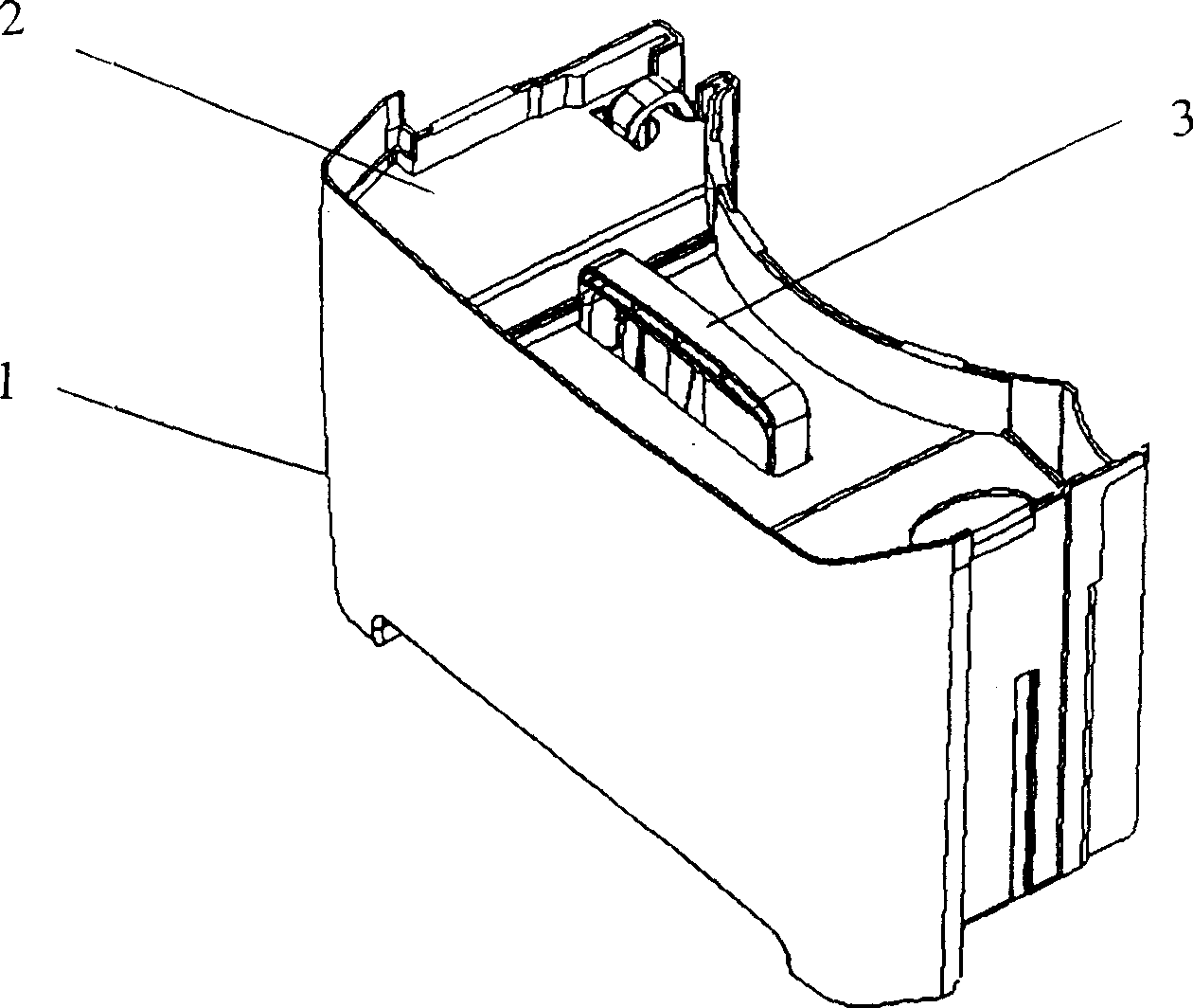
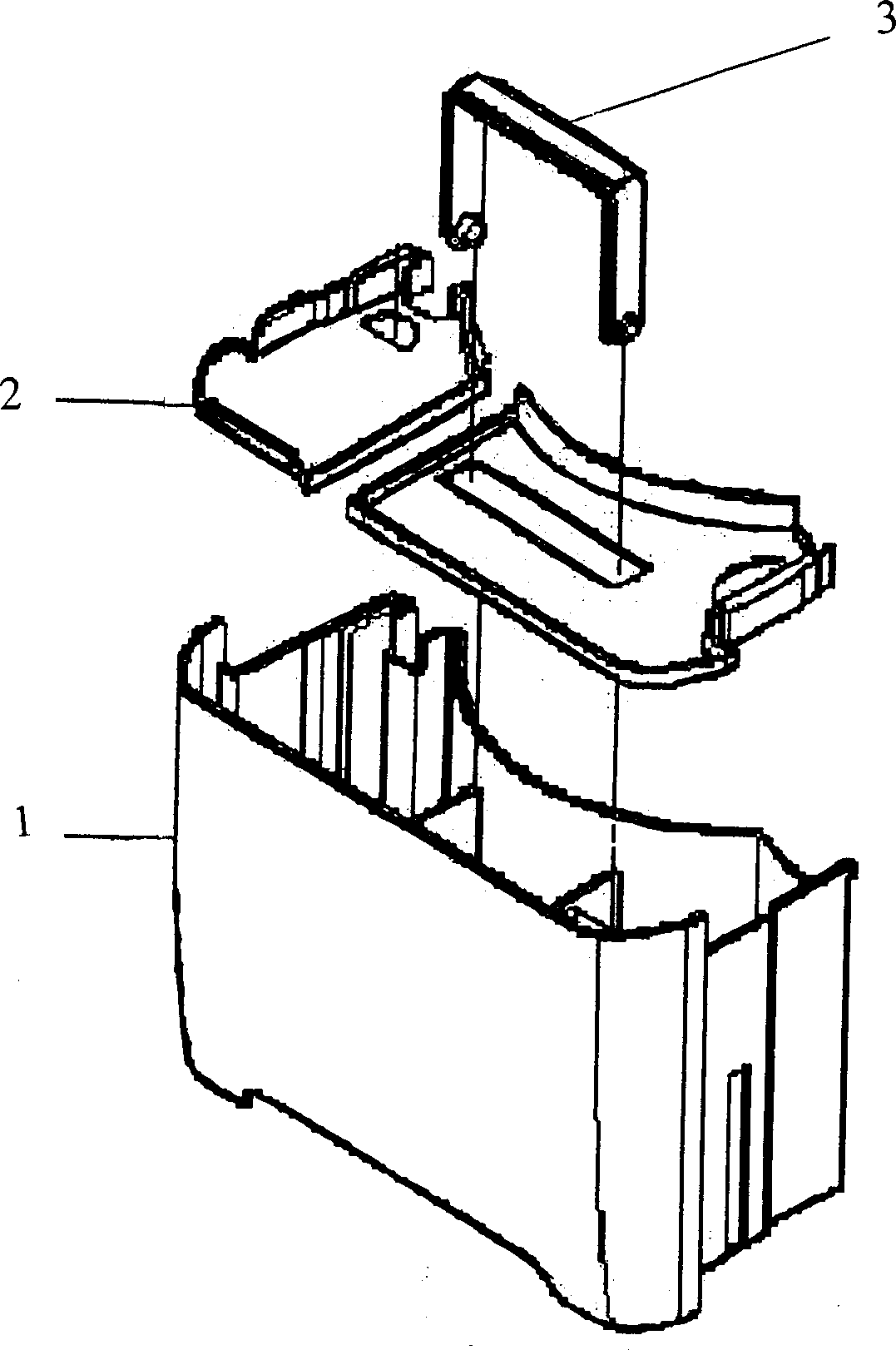
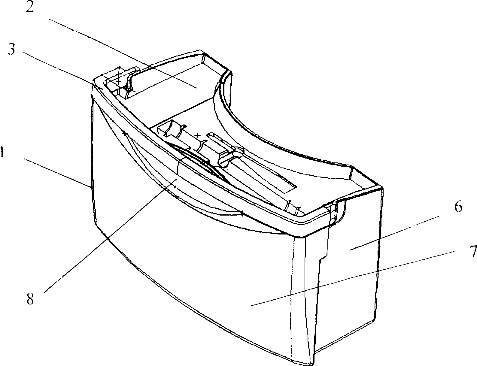
[0021] Such as image 3 with Figure 4 As shown, the two ends of the dehumidifier bucket handle 3 involved in the present invention are rotatably connected to the upper ends of the two side walls 6 of the bucket, and can be laid down on the upper end of the front wall 7 of the bucket. Promptly handle 3 two ends respectively have a protrusion 4, insert in the jack 5 of bucket side wall 6 upper ends, the protrusion 4 at handle two ends can rotate in the jack 5 of bucket side wall 6. The handle 3 placed on the upper end of the bucket front wall 7 stretches out ahead of the front wall, and the front wall 7 has an arc-shaped groove 8 in the middle of the upper end.


PUM


Abstract

The invention discloses a dehumidifier bucket handle structure of front-plug type, which is characterized by the following parts: plugging two ends of handle projection in the jack on the top of bucket side wall; connecting two ends of handle on the top of bucket side wall and front wall with handle extending forward; putting the hand in the arc flute of front wall top end center when needing to pour condensing water; pulling the handle out of the dehumidifier; turning the handle uprightly. The invention is convenient to put and gain bucket and pour condensing water for user, which improves the producing and working efficiency.

Description

technical field [0001] The invention relates to a dehumidifier, in particular to a water bucket for the dehumidifier to hold condensed water. Background technique [0002] Generally speaking, after the dehumidifier sucks the humid air in the room into the dehumidifier body, it reduces the humidity through a heat exchanger composed of a condenser and an evaporator with a refrigerant flowing inside, and then redischarges the air with reduced humidity. Back to the indoor installation. The evaporation of the liquid refrigerant in the evaporator of the dehumidifier will cause the temperature of the evaporator to drop and absorb the heat in the surrounding air, so that the moisture contained in the humid air around the evaporator will condense and form water droplets on the surface of the evaporator to achieve dehumidification. Effect. The fan inside the dehumidifier continuously blows humid air around the evaporator, and the evaporator also continuously has condensed water form...

Claims


Application Information

Patent Timeline
IPC IPC(8): F24F3/14F24F13/22
Inventor 杨佩元张可孙哲郑宇辉
Owner LG ELECTRONICS (TIANJIN) APPLIANCES CO LTD
Why Eureka
Try Eureka