
Burning chamber of IC engine

A technology for combustion chambers and internal combustion engines, applied to internal combustion piston engines, combustion engines, mechanical equipment, etc., can solve the problems of unevenness, short penetrating distance of umbrella-shaped spray, and too thick circular distribution of mixed gas, so as to achieve fast spray dispersion speed, Large spatial range of distribution and improvement of emission indicators

Inactive Publication Date: 2004-12-15
DALIAN UNIV OF TECH
View PDF0 Cites 3 Cited by
  • Summary
  • Abstract
  • Description
  • Claims
  • Application Information

AI Technical Summary

Problems solved by technology

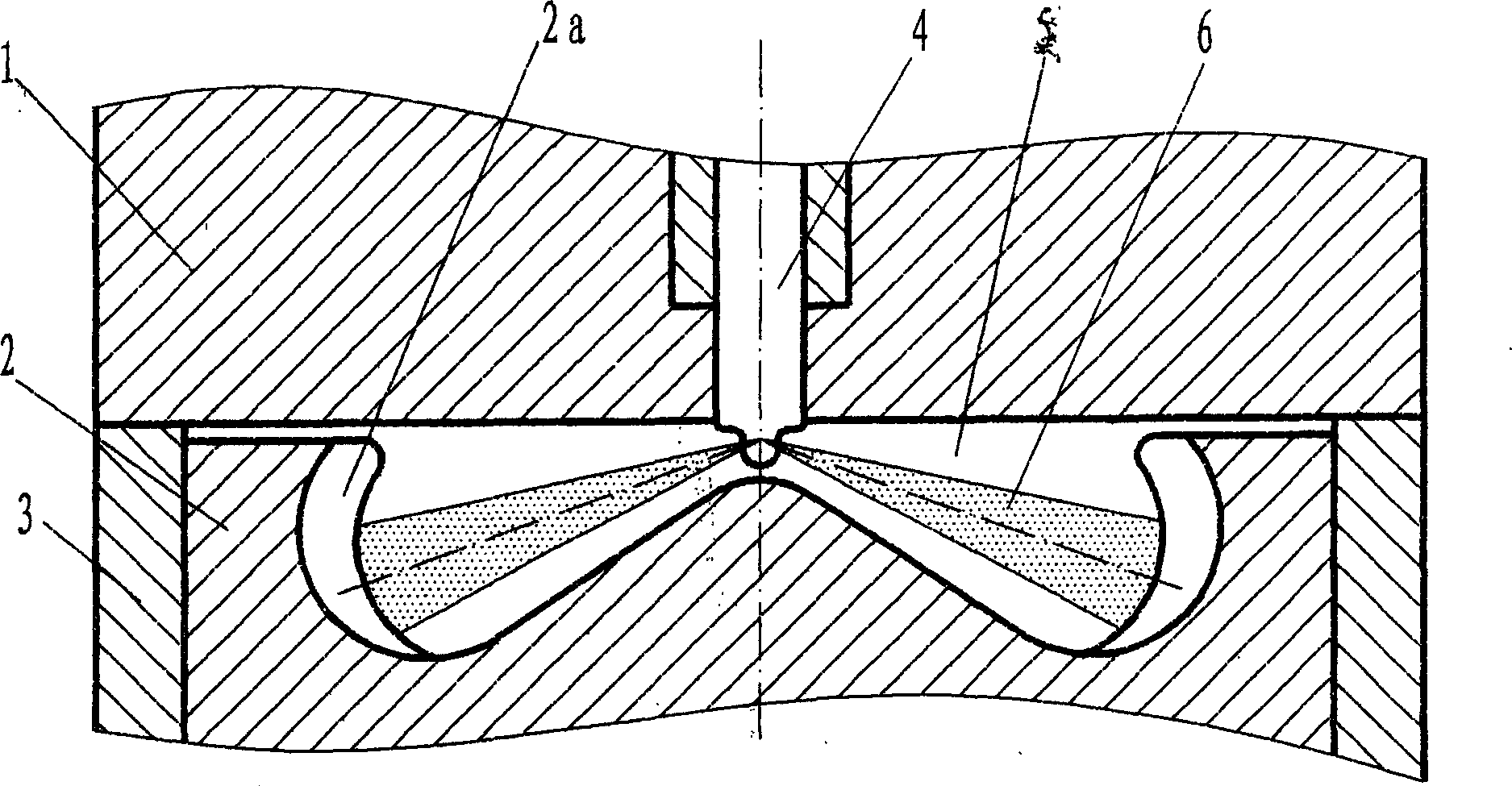
[0003] In order to solve the problems of too thick mixed gas and uneven distribution of the circular spray at the landing point of the porous spray, and the short penetrating distance of the umbrella-shaped spray, the present invention provides a combustion chamber of an internal combustion engine, which can improve the atomization performance and improve the spray efficiency. The space is evenly distributed, the spray will not accumulate at the landing point, but part of it will be rebounded, and the part will be quickly dispersed along the guide surface to achieve secondary atomization

Method used


Image

  • Burning chamber of IC engine
  • Burning chamber of IC engine

Examples


Embodiment Construction

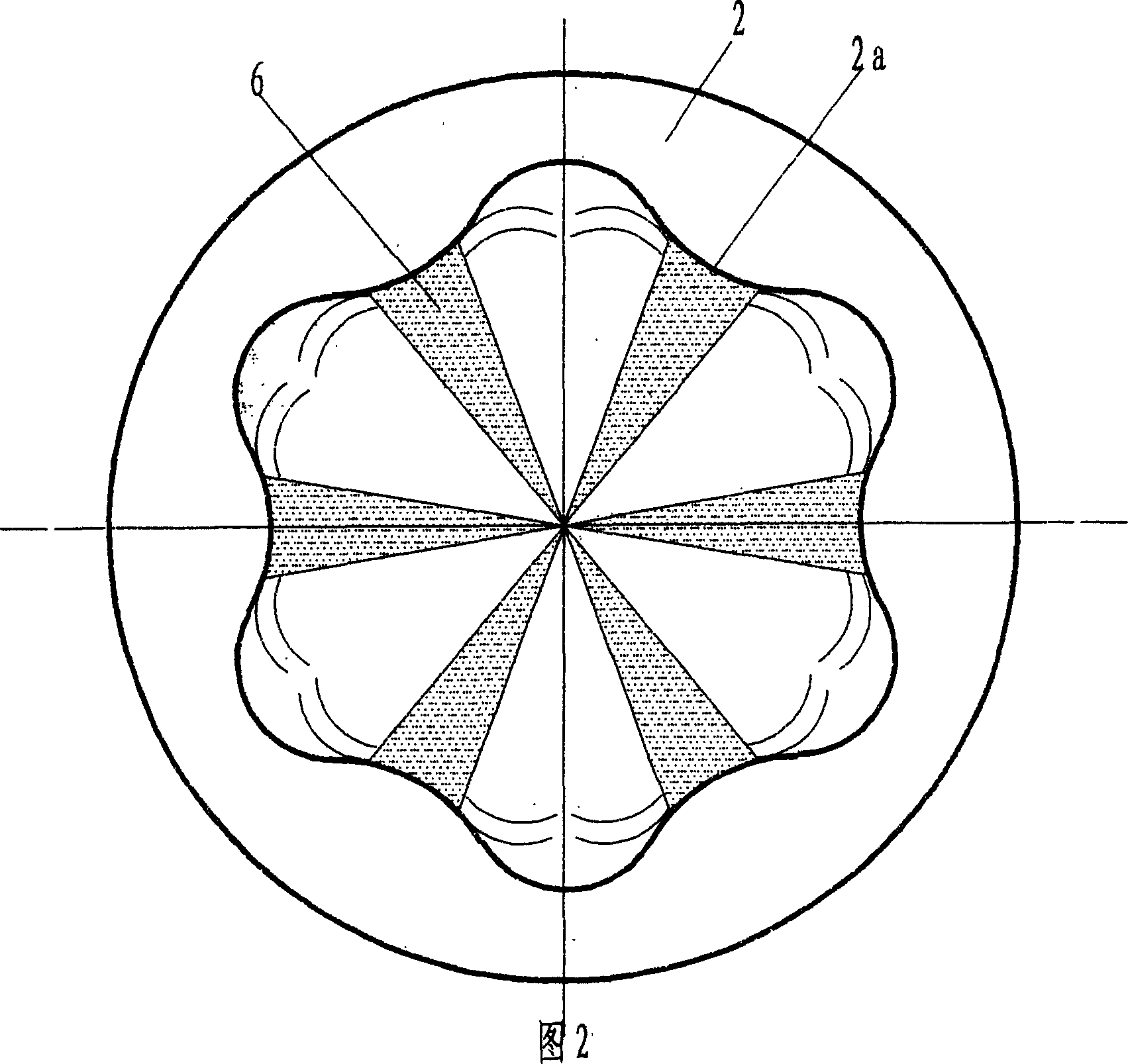
[0010] exist figure 1 , In the embodiment shown in 2, in the combustion chamber (5) that is made up of cylinder head (1), piston (2) and cylinder liner (3), be provided with 6 spray collisions on the inner wall of combustion chamber (5) ridge (2a), the 6 mist oil beams (6) sprayed out by the injector (4) are just facing the 6 collision ridges (2a), because the collision ridge (2a) has a profile suitable for spray flow, in the main During the upward movement of the piston (2) in the oil injection stage, each oil beam falls on the top, middle, and bottom of the collision ridge in turn, part of the spray is rebounded, and part of the spray is quickly dispersed along the guiding arcs on both sides of the collision ridge, realizing the secondary Atomization.


PUM


Abstract

The present invention relates to a kind of burning chamber of internal combustion engine and belongs to the field of engine mixed gas formation and combustion. The burning chamber has in the inner wall of piston top spraying collision ridges in the number corresponding to the jetted oil beams, and the collision ridges have proper profile for spraying flow, so that one part of the spray is dispersed fast along the guide arc to atomize for the second time while the other part is rebounded. So, homogeneous inflammable mixed gas is formed fast for complete and fast combustion without needing great air eddy current. The engine is improved in exhaust performance obviously while the economic performance and power indexes are raised.

Description

technical field [0001] The invention relates to a combustion chamber of an internal combustion engine, which belongs to the field of formation and combustion of engine mixture gas. Background technique [0002] At present, the excess air coefficient of the diesel engine is relatively large, but it is easy to emit black smoke. The main reason is that the porous spray is not uniform in the circumferential direction, and an over-concentrated area is generated at the spray point. A part of the spray accumulates near the impact point or forms an oil film, and the other part rebounds and diffuses in the circumferential direction, so that the amount of air entrained close to the wall of the combustion chamber is small. These factors constitute the main cause of carbon formation on the wall of the combustion chamber despite the large excess air coefficient of the diesel engine, but the incomplete combustion, black smoke and high hydrocarbon emissions. In order to solve this problem...

Claims


Application Information

Patent Timeline
Patent Type & Authority Applications(China)
IPC IPC(8): F02B23/00F02B55/14
CPCY02T10/125Y02T10/12
Inventor 隆武强
Owner DALIAN UNIV OF TECH
Learn More